- 您現在的位置:買賣IC網 > PDF目錄360971 > IRPT2051 PDF資料下載
參數資料
| 型號: | IRPT2051 |
| 文件頁數: | 7/12頁 |
| 文件大小: | 126K |
| 代理商: | IRPT2051 |
page 7
IRPT2051
Mounting, Hookup and Application Instructions
Mounting
1. Remove all particles and grit from the heat sink and power
substrate.
2. Spread a .004" to .005" layer of silicone grease on the heat
sink, covering the entire area that the power substrate will oc-
cupy. Recommended heat sink flatness is .001 inch/inch and
Total Indicator Readout (TIR) of .003" below substrate.
3. Place the power substrate onto the heat sink with the
mounting holes aligned and press it firmly into the silicone
grease.
4. Place the 2 M4 mounting screws through the PCB and
power module and into the heat sink and tighten the screws to
1 Nm torque.
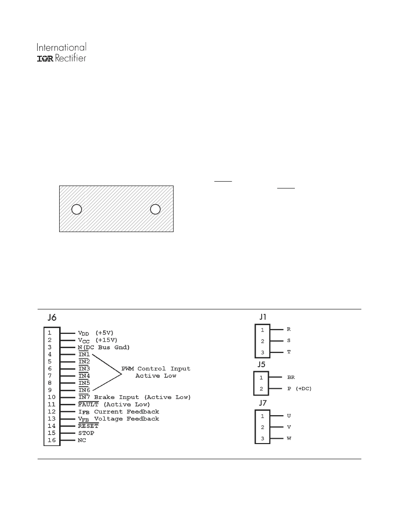
Control Connections
All input and output connections are made via a 16-terminal fe-
male connector to J6.
Figure 6. Power Assembly Mounting Screw Sequence
1234567890123456789012345678901212
1234567890123456789012345678901212
1234567890123456789012345678901212
1234567890123456789012345678901212
1234567890123456789012345678901212
1234567890123456789012345678901212
1234567890123456789012345678901212
1234567890123456789012345678901212
1234567890123456789012345678901212
1234567890123456789012345678901212
1234567890123456789012345678901212
1234567890123456789012345678901212
1234567890123456789012345678901212
1234567890123456789012345678901212
Power Connections
3-phase input connections are made to terminals R, S and T (J1).
Inverter output terminal connections are made to terminals U, V
and W (J7).
Positive DC bus and Brake IGBT collector connections are
brought out to terminals P (positive) and BR (brake) of J5 con-
nector. An external resistor for braking can be connected across
these terminals.
Power-Up Procedure
When 3-phase input power is first switched on, PWM inputs to
the IRPT2051 must be inhibited (held high) until the protection
latch circuitry is reset. To reset this latch before inverter start-
up, RESET pin on J6 connector must be pulled down low for at
least 2 μsec. This will set the FAULT feedback signal high.
Now, the PWM input signals can be applied for inverter start-up.
Power-Down Procedure
The following sequence is recommended for normal power
down:
1. reduce motor speed by PWM control
2. inhibit PWM inputs
3. disconnect main power.
Figure 7a. Control Signal Connector
Figure 7b. Input and Output Terminal Blocks
相關PDF資料 |
PDF描述 |
|---|---|
| IRPT2051A | |
| IRPT2055 | |
| IRPT2055A | |
| IRPT2060A | |
| IRPT2062 | |
相關代理商/技術參數 |
參數描述 |
|---|---|
| IRPT2051A | 制造商:未知廠家 制造商全稱:未知廠家 功能描述: |
| IRPT2055 | 制造商:未知廠家 制造商全稱:未知廠家 功能描述: |
| IRPT2055A | 制造商:未知廠家 制造商全稱:未知廠家 功能描述: |
| IRPT2056 | 制造商:IRF 制造商全稱:International Rectifier 功能描述:Power Module for 3 hp Motor Drives |
| IRPT2056A | 制造商:IRF 制造商全稱:International Rectifier 功能描述:Power Module for 3 hp Motor Drives |
發布緊急采購,3分鐘左右您將得到回復。