- 您現在的位置:買賣IC網 > PDF目錄360971 > IRPT2055 PDF資料下載
參數資料
| 型號: | IRPT2055 |
| 文件頁數: | 3/12頁 |
| 文件大小: | 126K |
| 代理商: | IRPT2055 |
page 3
IRPT2051
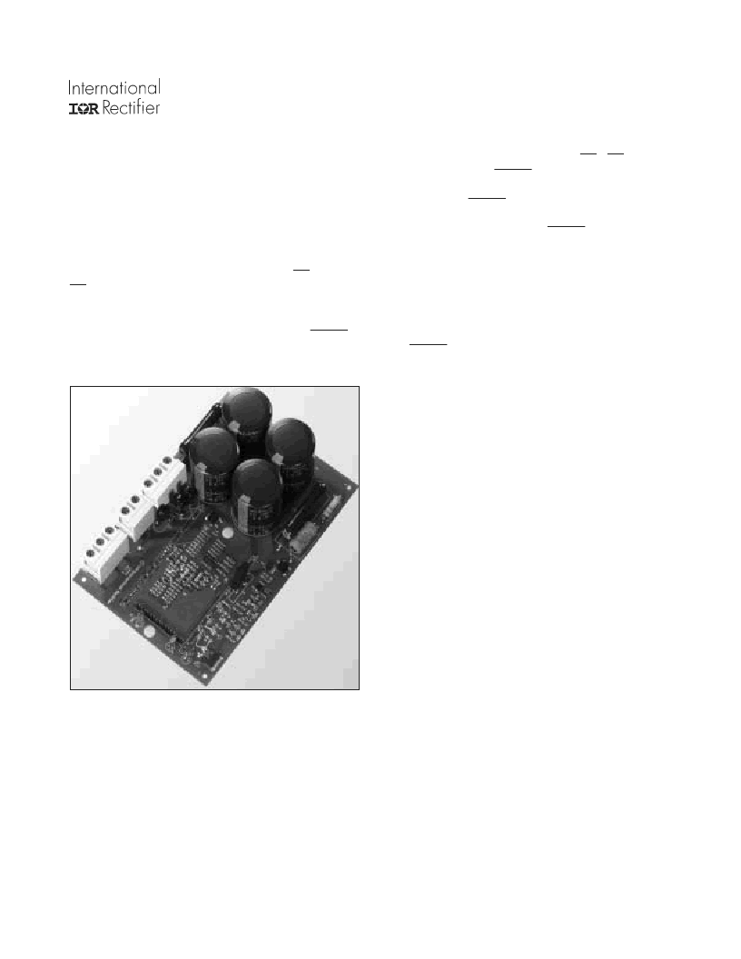
The IRPT2051D Driver-Plus Board
The Driver-
Plus
Board, shown in figure 3, is the interface be-
tween the controller and the power stage. It contains the IGBT
gate drivers, protection circuitry, feedback, brake drive and local
power supply. The driver also interfaces to the AC input line. It
houses the DC link capacitors, NTC in-rush limiting thermistor,
and surge suppression MOVs.
The inverter
gate drive circuits,
implemented with an
IR2233 monolithic 3-phase HVIC driver, deliverrs gate drive to
the IGBTs corresponding to PWM control signals IN1 through
IN6. it introduces a 0.2 μsec dead time between upper and lower
gate signals for each phase. Any additional dead time necessary
tmust be included in the PWM signals. After a fault condition
all inverter gate drivers are disabled and latched. The FAULT
pin is also pulled low through an open drain which illuminates a
red LED. Gate drives must be enabled with an active low pulse
applied to the RESET pin while PWM inputs In1,...IN6 are held
high (off condition). The FAULT condition can also be set by
the controller through an active high signal on the STOP pin.
After power-up, the RESET pin must be pulled low before any
input signals are activated.
The
protection circuitry
will set a FAULT for short-circuit,
earth-fault, over-temperature, or over-voltage conditions as
specified. Current signals are sensed through shunts in positive
and negative DC bus rails. Earth faults are sensed using the
high-side shunt and the signal is fed through an opto-isolator to
the protection circuitry. Over-voltage is sensed through a resis-
tor divider from the positive DC bus. Over-temperature
protection is obtained using a thermistor inside the power mod-
ule. A FAULT condition occurs inf the temperature of the
power module's IMS substrate exceeds the trip level. The sys-
tem is designed for 150% overload for one minute while
operating with the specified heat sinks. The controller should
shut off the PWM signals if the overload persists for more than
one minute.
The
feedback signals
used by the protection circuitry are also
available to the controller. The current feedback signal from the
low-side shunt is available on the IFB pin at 0.025 V/A. If filter-
ing of this signal is required, it should be done by adding a
high-impedance buffer stage between signal and filter. The DC
bus reference is provided on VFB. This reference has been
scaled down by a factor of 100 and should also be protected with
a high-impedance buffer stage.
The
brake function
is implemented by connecting a power
resistor between the terminals on the Brake terminal block. The
value and power of theresistor determines maximum braking ca-
pability along with the rating of the brake IGBT. The input
signal on IN7 is active low and CMOS or LSTTL compatible.
The
switching power supply
employs an IR2152 self-oscil-
lating driver chip in a buck regulator topology to deliver a
nominal 15V and 5V DC with respect to the negative bus (N).
The power supply feeds the gate drive and protection circuits.
The 15V (V
CC
) and 5V (V
DD
) outputs are available on the con-
trol interface for powering the user's control logic.
Figure 3. IRPT2051D Driver-PlusBoard
相關PDF資料 |
PDF描述 |
|---|---|
| IRPT2055A | |
| IRPT2060A | |
| IRPT2062 | |
| IRPT2064A | |
| IRPT2051 | Integrated Power Stage for 2.2kW Motor Drives(2.2kW 馬達驅動器的集成功率單元) |
相關代理商/技術參數 |
參數描述 |
|---|---|
| IRPT2055A | 制造商:未知廠家 制造商全稱:未知廠家 功能描述: |
| IRPT2056 | 制造商:IRF 制造商全稱:International Rectifier 功能描述:Power Module for 3 hp Motor Drives |
| IRPT2056A | 制造商:IRF 制造商全稱:International Rectifier 功能描述:Power Module for 3 hp Motor Drives |
| IRPT2059A | 制造商:IRF 制造商全稱:International Rectifier 功能描述:Power Module for 2 hp Motor Drives |
| IRPT2060A | 制造商:IRF 制造商全稱:International Rectifier 功能描述:Power Module for 3 hp Motor Drives |
發布緊急采購,3分鐘左右您將得到回復。