- 您現在的位置:買賣IC網 > PDF目錄360996 > ISO102B SIGNAL ISOLATION BUFFER AMPLIFIERS PDF資料下載
參數資料
| 型號: | ISO102B |
| 英文描述: | SIGNAL ISOLATION BUFFER AMPLIFIERS |
| 中文描述: | 信號隔離緩沖放大器 |
| 文件頁數: | 10/15頁 |
| 文件大小: | 230K |
| 代理商: | ISO102B |
10
ISO102/106
PRINTED CIRCUIT BOARD LAYOUT
The distance across the isolation barrier, between external
components, and conductor patterns, should be maximized
to reduce leakage and arcing at high voltages. Good layout
techniques that reduce stray capacitance will assure low
leakage current and high AC IMR. For some applications,
applying conformal coating compound such as urethane is
useful in maintaining good performance. This is especially
true where dirt, grease or moisture can collect on the PC
board surface, component surface, or component pins. Fol-
lowing this industry-accepted practice will give best results,
particularly when circuits are operated or tested in a mois-
ture-condensing environment. Optimum coating can be
achieved by administering urethane under vacuum condi-
tions. This allows complete coverage of all areas. Grounded
rings around the C
and C
contacts on the board greatly
reduce high voltage electric fields at these pins.
APPLICATIONS
The ISO102 and ISO106 isolation amplifiers are used in
three categories of applications:
1. accurate isolation of signals from high voltage ground
potentials,
2. accurate isolation of signals from severe ground noise,
and
3. fault protection from high voltages in analog measure-
ment systems.
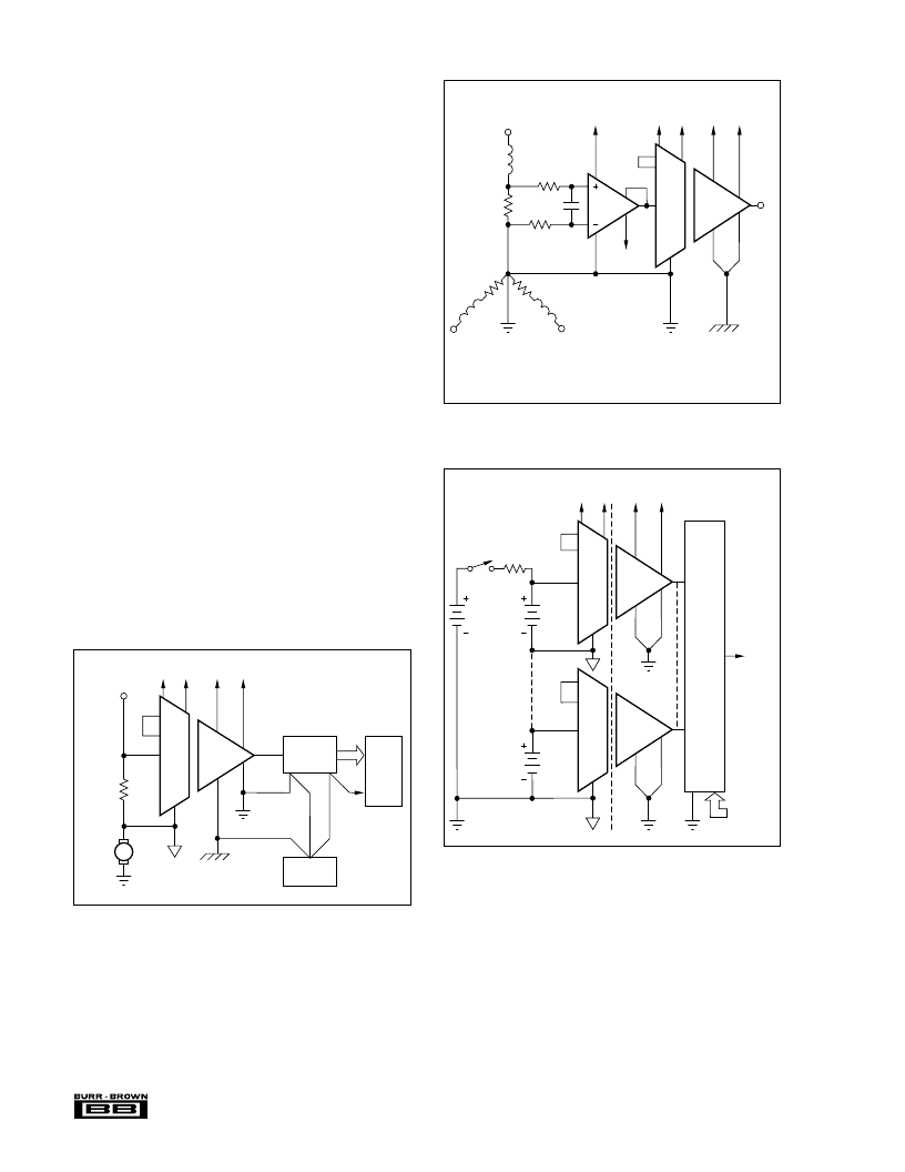
Figures 5 through 15 show a variety of application circuits.
Additional discussion of applications can be found in the
December 11, 1986 issue of
Electronic Design,
pages 91-96.
FIGURE 5. Isolated Power Current Monitor for Motor Cir-
cuit. (The ISO102 allows reliable, safe measure-
ment at high voltages.)
Data
Bus
ISO
102
+500VDC
100A
21
22
2
1V
0.01
4
16
10
14
V
IN
ADC574
13
12
Digital
Ground
Power
Supply
Analog
Ground
Plane
1
–5V
1
+5V
1
–5V
1
+5V
24
1
Y-Connected
Power Transformer
ISO
102
21
22
4
10
16
14
V
OUT
13
12
1
–5V
1
+5V
1
–5V
1
+5V
24
1
120Vrms
100A
10
INA1
0.005
Power
Resistor
0.5V
0.001μF
200k
200k
–15V
6
7
9
1
2
8
10
1
+5V
Differential input accurately senses power resistor voltage.
Two resistors protect INA110 from open power resistor.
High frequency spike reject filter has f = 400Hz.
2
FIGURE 6. Isolated Power Line Monitor (0.5
μ
A leakage
current at 120Vrms).
FIGURE 7. Battery Monitor for High Voltage Charging
Circuit.
ISO
102
21
22
4
10
16
14
13
12
1
–5V
1
+5V
1
–5V
1
+5V
24
1
2
Address
Selects
Battery
to be
Measured
MPC8S
Multi-
plexer
+720V
12V
750V
60
B
60
ISO
102
V
Monitor
to ADC
and
Computer
R
B
1
+708V
1
相關PDF資料 |
PDF描述 |
|---|---|
| ISO106 | SIGNAL ISOLATION BUFFER AMPLIFIERS |
| ISO106B | SIGNAL ISOLATION BUFFER AMPLIFIERS |
| ISO102 | SIGNAL ISOLATION BUFFER AMPLIFIERS |
| ISO103 | Low-Cost, Internally Powered ISOLATION AMPLIFIER |
| ISO103B | Low-Cost, Internally Powered ISOLATION AMPLIFIER |
相關代理商/技術參數 |
參數描述 |
|---|---|
| ISO103 | 功能描述:特殊用途放大器 Low-Cost Internally Pwrd Iso Amp RoHS:否 制造商:Texas Instruments 通道數量:Single 共模抑制比(最小值): 輸入補償電壓: 工作電源電壓:3 V to 5.5 V 電源電流:5 mA 最大功率耗散: 最大工作溫度:+ 70 C 最小工作溫度:- 40 C 安裝風格:SMD/SMT 封裝 / 箱體:QFN-20 封裝:Reel |
| ISO103 | 制造商:Texas Instruments 功能描述:IC AMP ISOLATION DIP24 103 |
| ISO103B | 功能描述:特殊用途放大器 Low-Cost Internally Pwrd Iso Amp RoHS:否 制造商:Texas Instruments 通道數量:Single 共模抑制比(最小值): 輸入補償電壓: 工作電源電壓:3 V to 5.5 V 電源電流:5 mA 最大功率耗散: 最大工作溫度:+ 70 C 最小工作溫度:- 40 C 安裝風格:SMD/SMT 封裝 / 箱體:QFN-20 封裝:Reel |
| ISO1050 | 制造商:TI 制造商全稱:Texas Instruments 功能描述:ISOLATED CAN TRANSCEIVER |
| ISO1050_10 | 制造商:TI 制造商全稱:Texas Instruments 功能描述:ISOLATED CAN TRANSCEIVER |
發布緊急采購,3分鐘左右您將得到回復。