- 您現在的位置:買賣IC網 > PDF目錄367494 > L8574D CAP 15PF 50V 5% C0G SMD-0402 TR-7-PA SN100 PDF資料下載
參數資料
| 型號: | L8574D |
| 英文描述: | CAP 15PF 50V 5% C0G SMD-0402 TR-7-PA SN100 |
| 中文描述: | L8574D電阻用戶線接口電路(SLIC),環繼電器和保護(SRP)的為遠距離和TR - 57應用 |
| 文件頁數: | 9/36頁 |
| 文件大小: | 489K |
| 代理商: | L8574D |
第1頁第2頁第3頁第4頁第5頁第6頁第7頁第8頁當前第9頁第10頁第11頁第12頁第13頁第14頁第15頁第16頁第17頁第18頁第19頁第20頁第21頁第22頁第23頁第24頁第25頁第26頁第27頁第28頁第29頁第30頁第31頁第32頁第33頁第34頁第35頁第36頁
Lucent Technologies Inc.
9
Data Sheet
October 1998
Relay, and Protector (SRP) for Long Loop and TR-57 Applications
L8574D Resistive Subscriber Line Interface Circuit (SLIC), Ring
Electrical Characteristics
(continued)
Fault Protection
Pins PT, PR, and V
BF
Pins PT, PR, and V
BF
are protected by SCRs which clamp surge currents (both positive and negative) to FGND. If
the SCR on PR or V
BF
triggers due to a negative surge, the L8574 automatically switches to the disconnect state
while the SCR is conducting current above its hold current. After the SCR releases, the L8574 automatically
switches back to the operating state prior to the SCR trigger.
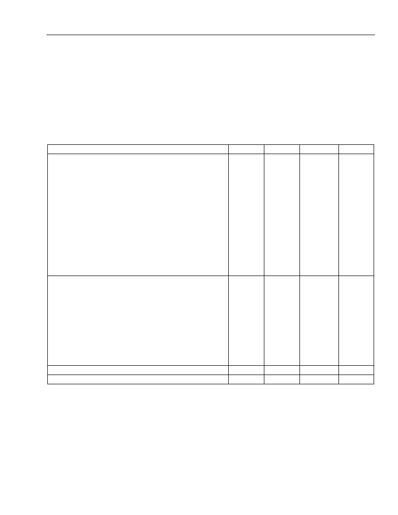
Table 5. Electrical Characteristics of Pins PT, PR, and V
BF
1.This parameter is not tested in production. It is guaranteed by design and device characterization.
2.Applied voltage is 50 Vpp square wave at 100 Hz to measure dV/dt sensitivity.
Parameter
Min
Typ
Max
Unit
PT and PR:
Surge Current
1
:
Lightning—10
μ
s x 1000
μ
s
Lightning—2
μ
s x 10
μ
s
Power Cross—60 Hz, 50 ms
Power Cross—60 Hz, 1 s
Power Cross—60 Hz, 15 min.
SCR Trigger Voltage Pin PT:
Positive
Negative
dc Transient Response
SCR Trigger Voltage Pin PR:
Positive
Negative
SCR Hold Current (positive and negative)
V
BF
:
Surge Current
1
:
Lightning—10
μ
s x 1000
μ
s
Lightning—2
μ
s x 10
μ
s
Power Cross—60 Hz, 50 ms
Power Cross—60 Hz, 1 s
Power Cross—60 Hz, 15 min.
SCR Trigger Voltage:
Positive
Negative
SCR Hold Current (positive and negative)
Trigger Current (if from a power supply—PT, PR, and V
BF
)
dV/dt Sensitivity
1, 2
(PT, PR, and V
BF
)
—
—
—
—
—
—
—
—
—
—
±
1
±
2.5
600
200
50
A
A
mArms
mArms
mArms
V
CCA
– 2
–25
–25
—
—
—
V
CCA
+ 4
–35
–55
V
V
V
150
–220
10
—
—
—
280
320
—
V
V
mA
—
—
—
—
—
—
—
—
—
—
±
5.5
±
13
3
800
150
A
A
Arms
mArms
mArms
150
–220
10
—
—
—
—
—
—
500
280
–320
—
±
250
—
V
V
mA
μ
A
V/
μ
s
相關PDF資料 |
PDF描述 |
|---|---|
| L8575 | Dual-Resistive,Low-Cost Subscriber Line Interface Circuit(SLIC) |
| L8576B | Dual Ringing SLIC |
| L8712(FECONLY) | IC TUBE FOR TO-220 508MM |
| L88R05_SERIES | |
| L8958-11SC | Optoelectronic |
相關代理商/技術參數 |
參數描述 |
|---|---|
| L8575 | 制造商:Leviton Manufacturing Co 功能描述: |
| L8576B | 制造商:AGERE 制造商全稱:AGERE 功能描述:Dual Ringing SLIC |
| L8576BP | 制造商:Alcatel-Lucent 功能描述: 制造商:LUCENT 功能描述: |
| L85J250E | 制造商:Ohmite Mfg Co 功能描述: |
| L8601-01 | 制造商:HAMAMATSU 制造商全稱:Hamamatsu Corporation 功能描述:90KV MICROFOCUS X-RAY SOURCE |
發布緊急采購,3分鐘左右您將得到回復。