- 您現在的位置:買賣IC網 > PDF目錄30720 > LA71586M SPECIALTY CONSUMER CIRCUIT, PQFP100 PDF資料下載
參數資料
| 型號: | LA71586M |
| 元件分類: | 消費家電 |
| 英文描述: | SPECIALTY CONSUMER CIRCUIT, PQFP100 |
| 封裝: | 14 X 20 MM, QIP-100 |
| 文件頁數: | 45/50頁 |
| 文件大小: | 1782K |
| 代理商: | LA71586M |
第1頁第2頁第3頁第4頁第5頁第6頁第7頁第8頁第9頁第10頁第11頁第12頁第13頁第14頁第15頁第16頁第17頁第18頁第19頁第20頁第21頁第22頁第23頁第24頁第25頁第26頁第27頁第28頁第29頁第30頁第31頁第32頁第33頁第34頁第35頁第36頁第37頁第38頁第39頁第40頁第41頁第42頁第43頁第44頁當前第45頁第46頁第47頁第48頁第49頁第50頁
LA71586M
No.A0223-5/50
Continued from preceding page.
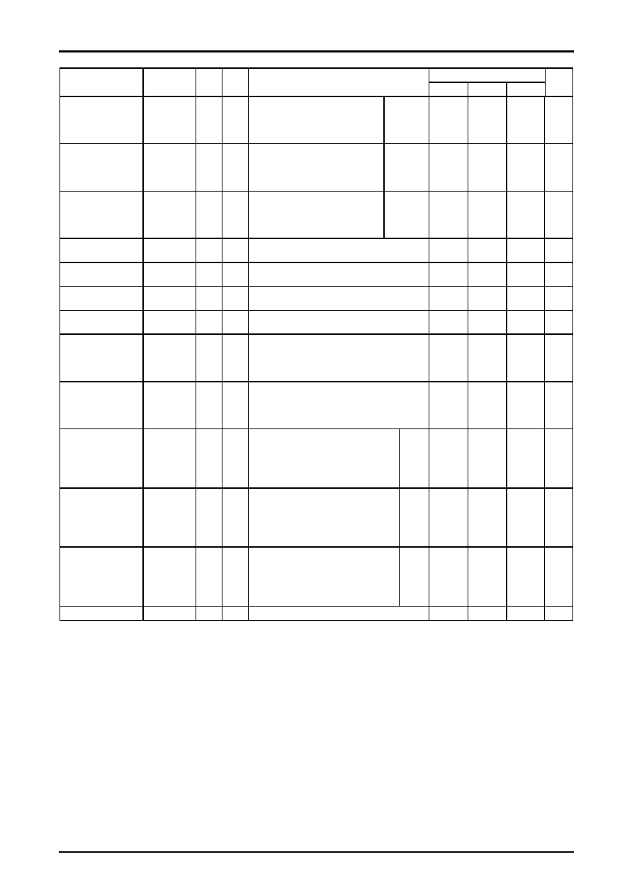
Ratings
Parameter
Symbol
In
Out
Conditions
min
typ
max
Unit
Double
noisecanceller
characteristics (1)
GWNC1
T20A
T29
f = 1.4MHz, 158mVp-p
Serial
000: MIN
100: TYP
111: MAX
-3.5
-2.5
-1.5
dB
Double
noisecanceller
characteristics (2)
GWNC2
T20A
T29
f = 1.4MHz, 50mVp- p
Serial
000: MIN
100: TYP
111: MAX
-12
-10
-8
dB
Double
noisecanceller
characteristics (3)
GWNC3
T20A
T29
f = 1.4MHz, 15.8mVp-p
Serial
000: MIN
100: TYP
111: MAX
-15
-13
-11
dB
PIC-CTL
Hard MAX
GPH1
T20A
T29
f = 2.5MHz, 158mVp-p
6.0
7.0
8.0
dB
PIC-CTL
Soft MAX
GPSF
T20A
T29
f = 2.5MHz, 158mVp-p
-8.8
-6.8
-4.8
dB
Sync separator output
level
VSYP
T20A
T28
With VIN a 0.5Vp-p video signal, measure the output
pulse wave height on T28.
4.0
4.2
4.4
Vp-p
Sync separator output
pulse width
PWSYP
T20A
T28
With VIN a 0.5Vp-p video signal, measure the output
pulse width on T28.
4.35
4.65
4.95
s
Sync tip level
Pedestal level
white level
LVOR
T20A
T229 With VIN a 100% white 0.5 Vp-p signal, measure the
sync tip and pedestal and white levels on T29 video
output, and take these as LSYN LPED LWHT,
respectively.
Quasi-V insertion
level
VDP
T20A
T29
Measure the T29 DC voltage with 4.3V applied to
T27, and take this to be LVDP, and compute the
difference with LSYN measured above.
VDP = LSYN-LVDP
0
mV
Quasi-H insertion level
HDP
T20A
T29
Measure the T29 DC voltage with 3.6V
applied to T27, and take this to be LHDP,
and compute the difference with LPED
measured above.
HDP = LPED-LHDP
-270
mV
White insertion level
WHP
T20A
T29
Measure the T29 DC voltage with 1.5V
applied to T26,and take this to be LWHP,
and compute the difference with LWHT
measured
WHP = LWHT-LWHP
150
mV
Edge insertion level
EGP
T20A
T29
Measure the T29 DC voltage with 0.8V
applied to T26,and take this to be LEGP,
and compute the difference with LPED
measured
WHP = LPED-LEGP
-300
mV
Regulator
VREG
T39
Measure the T39 DC level.
3.9
4.1
4.3
V
相關PDF資料 |
PDF描述 |
|---|---|
| LA71586M | SPECIALTY CONSUMER CIRCUIT, PQFP100 |
| LA71598HM | SPECIALTY CONSUMER CIRCUIT, PQFP100 |
| LA71598HM | SPECIALTY CONSUMER CIRCUIT, PQFP100 |
| LA7160M | SPECIALTY CONSUMER CIRCUIT, PDSO16 |
| LA7161BM | SPECIALTY CONSUMER CIRCUIT, PDSO16 |
相關代理商/技術參數 |
參數描述 |
|---|---|
| LA7160M | 制造商:SANYO 制造商全稱:Sanyo Semicon Device 功能描述:VHF Band RF Modulator |
| LA7161BM | 制造商:SANYO 制造商全稱:Sanyo Semicon Device 功能描述:VHF Band RF Modulator (US3, 4ch, JPN1, 2ch,TWN13ch compatible) |
| LA7161BV | 制造商:SANYO 制造商全稱:Sanyo Semicon Device 功能描述:VHF Band RF Modulator (US3, 4ch, JPN1, 2ch,TWN13ch compatible) |
| LA7161NMTLM | 制造商:SANYO 功能描述:* |
| LA7161NV | 制造商:SANYO 制造商全稱:Sanyo Semicon Device 功能描述:VHF Band RF Modulator(SUPPORTS US 3,4CH, JPN 1,2CH, TWN 13CH) |
發布緊急采購,3分鐘左右您將得到回復。