- 您現在的位置:買賣IC網 > PDF目錄30725 > LA76818A (SANYO SEMICONDUCTOR CO LTD) AM/FM, AUDIO/VIDEO DEMODULATOR, PDIP54 PDF資料下載
參數資料
| 型號: | LA76818A |
| 廠商: | SANYO SEMICONDUCTOR CO LTD |
| 元件分類: | 接收器 |
| 英文描述: | AM/FM, AUDIO/VIDEO DEMODULATOR, PDIP54 |
| 封裝: | 0.600 INCH, DIP-54 |
| 文件頁數: | 37/44頁 |
| 文件大小: | 289K |
| 代理商: | LA76818A |
第1頁第2頁第3頁第4頁第5頁第6頁第7頁第8頁第9頁第10頁第11頁第12頁第13頁第14頁第15頁第16頁第17頁第18頁第19頁第20頁第21頁第22頁第23頁第24頁第25頁第26頁第27頁第28頁第29頁第30頁第31頁第32頁第33頁第34頁第35頁第36頁當前第37頁第38頁第39頁第40頁第41頁第42頁第43頁第44頁
LA76818A
No.8047-42/44
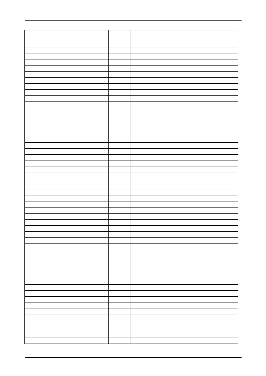
Control Register Descriptions
Register Name
Bits
General Description
T Disable
1
Disable the Test SW & enable Audio/Video Mute SW
AFC Gain & gate
1
Select horizontal first loop gain & H-sync gating on/off
H Freq.
6
Align ES Sample horizontal frequency
V Reset Timing
1
Select Vertical Reset Timing
Audio Mute
1
Disable audio outputs
Video Mute
1
Disable video outputs
H PHASE
5
Align sync to flyback phase
Sync Kill
1
Force free-run mode
Vertical Size
7
Align vertical amplitude
Vsep.up
1
Select vertical sync. separation sensitivity
Vertical Kill
1
Disable vertical output
V POSI (Vertical DC)
6
Align vertical DC bias
H BLK L
3
H-Blanking Control (Left side of the screen)
H BLK R
3
H-Blanking Control (Right side of the screen)
V LIN (Vertical Linearity)
5
Align vertical linearity
Vertical S-Correction
5
Align vertical S-correction
Vertical Test
2
Select vertical DAC test modes
Vertical Size Compensation
3
Align vertical size compensation
Count Down Mode
1
Select vertical countdown mode
Red Bias
8
Align Red OUT DC level
Green Bias
8
Align Green OUT DC level
Blue Bias
8
Align Blue OUT DC level
Red Drive
7
Align Red OUT AC level
Drive Test
1
Enable Drive control DAC test modes
Half Tone
2
Adjust half tone DC level
Half Tone Defeat
1
Half tone defeat SW
Green Drive
4
Align Green OUT AC level
A2.SW
1
Select 5.74MHz FM.Det
Blue Drive
7
Align Blue OUT AC level
Blank Def
1
Disable RGB output blanking
Sub Bias
7
Align common RGB DC level
A.MONI.SW
1
Select FM Output/Selected Audio Output
Brightness Control
7
Customer brightness control
S.TRAP.SW
1
Select Snd Trap bypass
Contrast Control
7
Customer contrast control
OSD Contrast Test
1
Enable OSD Contrast DAC test mode
OSD Contrast Control
2
Align OSD AC level
Coring Gain Select (with Defeat)
2
Select Coring Gain (0hex: Defeat)
Sharpness Control
6
Customer sharpness control
Tint Test
1
Enable tint DAC test mode
Tint Control
7
Customer tint control
Color Test
1
Enable color DAC test mode
Color Control
7
Customer color control
Video SW
1
Select Video source
Trap.Test
3
Trap Test
Filter System
3
Select Y/C Filter mode
Gray Mode
1
OSD Gray Tone Enable
Cross B/W
2
Service Test Mode (normal/Black/White/Cross)
CbCr_Input Enable SW
1
Enable CbCr Input (Disable SECAM Input)
G-Y Angle Select
1
Select G-Y Angle
Color Killer Operational Point Select
3
Select Color Killer Operational Point
Vertical Blanking SW
1
Select VBLK Period
Continued on next page.
相關PDF資料 |
PDF描述 |
|---|---|
| LA76835NM | AM/FM, AUDIO/VIDEO DEMODULATOR, PQFP80 |
| LA76835NM | AM/FM, AUDIO/VIDEO DEMODULATOR, PQFP80 |
| LA7685J | SPECIALTY CONSUMER CIRCUIT, PDIP64 |
| LA7688B | AM/FM, AUDIO/VIDEO DEMODULATOR, PDIP52 |
| LA7688 | AM/FM, AUDIO/VIDEO DEMODULATOR, PDIP52 |
相關代理商/技術參數 |
參數描述 |
|---|---|
| LA76820 | 制造商:未知廠家 制造商全稱:未知廠家 功能描述:單片多制式TV處理集成電路 |
| LA76828N | 制造商:SANYO 制造商全稱:Sanyo Semicon Device 功能描述:電視小信號處理芯片 |
| LA76828N-A-E | 制造商:Sony Semiconductor Solutions Division 功能描述: |
| LA76832N | 制造商:SANYO 制造商全稱:Sanyo Semicon Device 功能描述:Monolithic Linear IC I2C Bus Control IC |
| LA76835NM | 制造商:SANYO 制造商全稱:Sanyo Semicon Device 功能描述:Monolithic Linear IC I2C Bus Control IC |
發布緊急采購,3分鐘左右您將得到回復。