- 您現(xiàn)在的位置:買(mǎi)賣IC網(wǎng) > PDF目錄30725 > LA7688B AM/FM, AUDIO/VIDEO DEMODULATOR, PDIP52 PDF資料下載
參數(shù)資料
| 型號(hào): | LA7688B |
| 元件分類: | 接收器 |
| 英文描述: | AM/FM, AUDIO/VIDEO DEMODULATOR, PDIP52 |
| 封裝: | 0.600 INCH, DIP-52 |
| 文件頁(yè)數(shù): | 4/20頁(yè) |
| 文件大小: | 316K |
| 代理商: | LA7688B |
第1頁(yè)第2頁(yè)第3頁(yè)當(dāng)前第4頁(yè)第5頁(yè)第6頁(yè)第7頁(yè)第8頁(yè)第9頁(yè)第10頁(yè)第11頁(yè)第12頁(yè)第13頁(yè)第14頁(yè)第15頁(yè)第16頁(yè)第17頁(yè)第18頁(yè)第19頁(yè)第20頁(yè)
LA7688B
No.0077-12/20
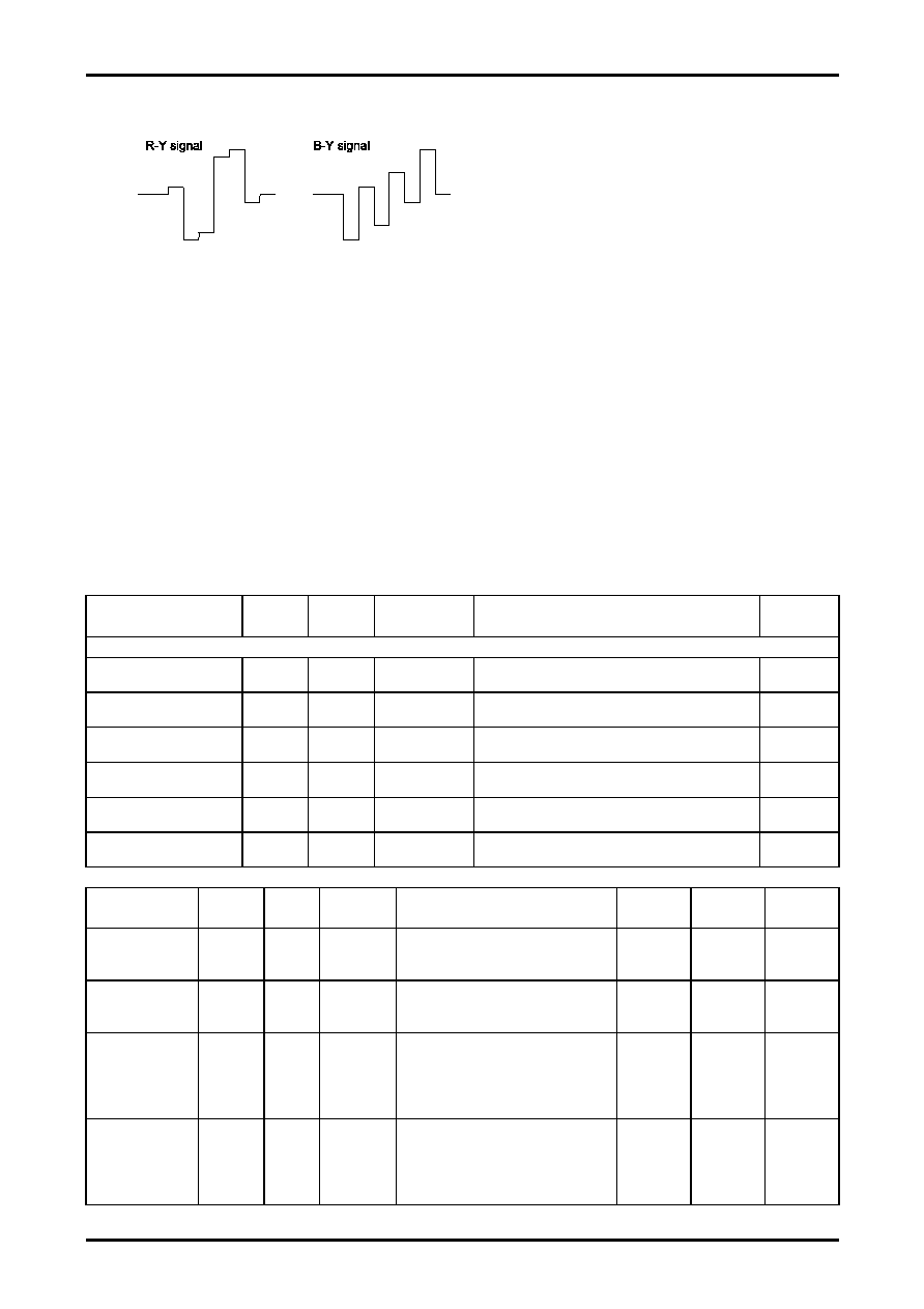
(5) SECAM signal
R-Y, B-Y demodulation signal
2. The chroma signal which is input from pin 13 (S-CHROMA IN) is assumed to be a PAL chroma signal.
INT/EXT SW block, SAB block, VIDEO SW block, FILTER block Input signals and test conditions
Set up the following conditions unless otherwise specified for each test item.
(VIF, SIF blocks : No signal)
1. Input signals
INT SECA --- INT IN (pin 10) 1Vp-p : SECAM color bar
INT PAL
--- INT IN (pin 10) 1Vp-p : PAL color bar
EXT PAL --- EXT IN (pin 14) 1Vp-p : PAL color bar
EXT SECA --- EXT IN (pin 14) 1Vp-p : SECAM color bar
EXT NT
--- EXT IN (pin 14) 1Vp-p : NTSC color bar
AUDIO IN --- EXT AUDIOIN (12pin) 1Vrms SIN wave (1kHz)
2. S-CHROMA IN (pin 13) : DC5V+Chroma signal
3. VR control position : Contrast VR-4V, sharpness VR-2V, others-control center
4. VCC, ICC conditions : VCC = 7.8V, ICC = 12mA.
Parameter
Symbol
Test
point
Input
conditions
Test method
V-SW
Pin 1
[INT/EXT SW block]
AFT EXT gain
GAF
O-51
EXT PAL
I-12
Measure the gain difference between input and output.
(f = 400Hz, 500mVrms)
3.3V
INT/EXT
crosstalk (AUDIO)
THDAF
O-51
EXT PAL
I-12
Measure the distortion factor of the output.
(f = 400Hz, 500mVrms)
3.3V
System SW I-SE
V1TH1
O-16A
O-39
INT SECA
Check to see that the selected signal is INT-SECAM.
0V
1.2V
System SW I-P/N
V1TH2
O-16A
O-39
INT PAL
Check to see that the selected signal is INT-PAL.
1.7V
2.6V
System SW E-P/N
V1TH3
O-16A
O-39
EXT PAL
Check to see that the selected signal is EXT-PAL.
2.9V
3.8V
System SW E-SE
V1TH4
O-16A
O-39
EXT SECA
Check to see that the selected signal is EXT-SECAM.
4.1V
5V
Parameter
Symbol
Test
point
Input
conditions
Test method
Contrast
Sharpness
Bright
Y signal frequency
characteristics (3)
(NTSC MODE)
BW3
O-32
f = variable
100mVp-p
Measure the frequency at which the
output level drops by 3dB relative to that
when f = 100kHz is set.
4V
1.8V
2.5V
DC transmission
ratio
DVAPL
O-32
White
100%
black
Measure the output pedestal level
variations when a white 100% signal and
a black signal are input.
4V
2V
2.5V
Black expansion
threshold
BSTH
O-33
I-14
Set S32 to ”B”.
Connect an oscilloscope to 0-33 and
measure the level of 5IRE expansion
when the RAMP signal APL is changed
for a range from 10% to 90%.
4V
2V
2.5V
Maximum black
expansion gain
Bsmax
O-33
I-14
Set S32 to ”B”.
Connect an oscilloscope to 0-33 and
measure the change in the pedestal level
when the RAMP signal APL is changed to
90%.
4V
2V
2.5V
相關(guān)PDF資料 |
PDF描述 |
|---|---|
| LA7688 | AM/FM, AUDIO/VIDEO DEMODULATOR, PDIP52 |
| LA76919M | SPECIALTY CONSUMER CIRCUIT, PQFP80 |
| LA76931K | SPECIALTY CONSUMER CIRCUIT, PDIP64 |
| LA76931K | SPECIALTY CONSUMER CIRCUIT, PDIP64 |
| LA76938Y | SPECIALTY CONSUMER CIRCUIT, PDIP64 |
相關(guān)代理商/技術(shù)參數(shù) |
參數(shù)描述 |
|---|---|
| LA76922M | 制造商:SANYO 制造商全稱:Sanyo Semicon Device 功能描述:Signal-Processing IC with Integrated Microcontroller |
| LA76930 | 制造商:SANYO 制造商全稱:Sanyo Semicon Device 功能描述:LA76930 |
| LA76931J7FB-E | 制造商:ON Semiconductor 功能描述:SIGNAL PROCESSING FOR CRT - Ammo Pack 制造商:ON Semiconductor 功能描述:FNFLD / SIGNAL PROCESSING FOR CRT |
| LA76931K7N5BD3-E | 制造商:Sony Semiconductor Solutions Division 功能描述: |
| LA76936Y7FB-E | 制造商:ON Semiconductor 功能描述:SIGNAL PROCESSING FOR CRT - Ammo Pack |
發(fā)布緊急采購(gòu),3分鐘左右您將得到回復(fù)。