- 您現在的位置:買賣IC網 > PDF目錄30728 > LB11696V (SANYO SEMICONDUCTOR CO LTD) BRUSHLESS DC MOTOR CONTROLLER, 0.03 A, PDSO30 PDF資料下載
參數資料
| 型號: | LB11696V |
| 廠商: | SANYO SEMICONDUCTOR CO LTD |
| 元件分類: | 運動控制電子 |
| 英文描述: | BRUSHLESS DC MOTOR CONTROLLER, 0.03 A, PDSO30 |
| 封裝: | 0.275 INCH, SSOP-30 |
| 文件頁數: | 6/16頁 |
| 文件大?。?/td> | 394K |
| 代理商: | LB11696V |
No.8087-14/16
LB11696V
Pulse Control Using the PWMIN Pin
A pulse signal can be input to the PWMIN pin, and the output can be controlled based on the duty of that signal.
Note that the output is on when a low level is input to the PWMIN pin, and off when a high level is input. When
the PWMIN pin is open it goes to the high level and the output is turned off. If inverted input logic is required,
this can be implemented with an external transistor (npn).
When controlling motor operation from the PWMIN pin, the EI– pin must be connected to ground, and the EI+
pin must be connected to the TOC pin.
Note that since the PWM oscillator is also used as the clock for internal circuits, a capacitor (about 2000 pF) must
be connected to the PWM pin even if the PWMIN pin is used for motor control.
6. Hall Input Signals
A signal input with an amplitude in excess of the hysteresis (80 mV maximum) is required for the Hall inputs.
Considering the possibility of noise and phase displacement, an even larger amplitude is desirable.
If disruptions to the output waveforms (during phase switching) or to the HP output (Hall signal output) occur due to
noise, this must be prevented by inserting capacitors across the inputs. The constraint protection circuit uses the Hall
inputs to discriminate the motor constraint state. Although the circuit is designed to tolerate a certain amount of
noise, care is required when using the constraint protection circuit.
If all three phases of the Hall input signal system go to the same input state, the outputs are all set to the off state
(the UL, VL, WL, UH, VH, and WH outputs all go to the low level).
If the outputs from a Hall IC are used, fixing one side of the inputs (either the + or – side) at a voltage within the
common-mode input voltage range allows the other input side to be used as an input over the 0 V to VCC range.
7. Undervoltage Protection Circuit
The undervoltage protection circuit turns one side of the outputs (UH, VH, and WH) off when the LVS pin voltage
falls below the minimum operation voltage (see the Electrical Characteristics). To prevent this circuit from
repeatedly turning the outputs on and off in the vicinity of the protection
operating voltage, this circuit is designed with hysteresis. Thus the output
will not recover until the operating voltage rises 0.45 V (typical).
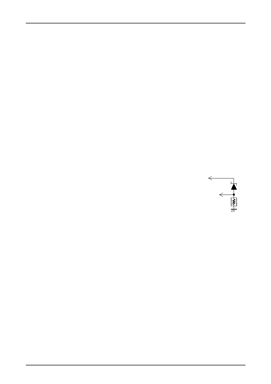
The protection operating voltage detection level is set up for 5 V systems.
The detected voltage level can be increased by shifting the voltage by
inserting a zener diode in series with the LVS pin to shift the detection
level. The LVS influx current during detection is about 75 A. To
increase the diode current to stabilize the zener diode voltage rise, insert
a resistor between the LVS pin and ground.
If the LVS pin is left open, the internal pull-down resistor will result in the IC seeing a ground level input, and the
output will be turned off. Therefore, a voltage in excess of the LVS circuit clear voltage (about 4.35 V) must be
applied to the LVS pin if the application does not use the undervoltage protection circuit. The maximum rating for
the LVS pin applied voltage is 18 V.
8. Constraint Protection Circuit
When the motor is physically constrained (held stopped), the CSD pin external capacitor is charged (to about 3.0 V)
by a constant current of about 2.5 A and is then discharged (to about 1.0 V) by a constant current of about 0.14 A.
This process is repeated, generating a sawtooth waveform. The constraint protection circuit turns motor drive on and
off repeatedly based on this sawtooth waveform. (The UH, VH, and WH side outputs are turned on and off.) Motor
drive is on during the period the CSD pin external capacitor is being charged from about 1.0 V to about 3.0 V, and
motor drive is off during the period the CSD pin external capacitor is being discharged from about 3.0 V to about
1.0 V. The IC and the motor are protected by this repeated drive on/off operation when the motor is physically
constrained.
The motor drive on and off times are determined by the value of the connected capacitor C (in F).
TCSD1 (drive on period)
≈ 0.8 × C (seconds)
TCSD2 (drive off period)
≈ 14.3 × C (seconds)
When a 0.47 F capacitor is connected externally to the CSD pin, this iterated operation will have a drive on period
of about 0.38 seconds and a drive off period of about 6.7 seconds.
To the power
supply detected
To the LVS pin
相關PDF資料 |
PDF描述 |
|---|---|
| LB11824M | BRUSHLESS DC MOTOR CONTROLLER, 0.04 A, PDSO30 |
| LB11851TT | BRUSH DC MOTOR CONTROLLER, 0.02 A, PDSO10 |
| LB11921T | BRUSHLESS DC MOTOR CONTROLLER, 0.01 A, PDSO36 |
| LB11921T | BRUSHLESS DC MOTOR CONTROLLER, 0.01 A, PDSO36 |
| LB11996H | DISK DRIVE MOTOR CONTROLLER, 1.3 A, PDSO28 |
相關代理商/技術參數 |
參數描述 |
|---|---|
| LB11696V-D | 制造商:SANYO 制造商全稱:Sanyo Semicon Device 功能描述:Direct PWM Drive Brushless Motor Predriver IC |
| LB11696VGEVB | 功能描述:電源管理IC開發(fā)工具 EVM FOR LB11696V RoHS:否 制造商:Maxim Integrated 產品:Evaluation Kits 類型:Battery Management 工具用于評估:MAX17710GB 輸入電壓: 輸出電壓:1.8 V |
| LB11696V-MPB-E | 功能描述:馬達/運動/點火控制器和驅動器 RoHS:否 制造商:STMicroelectronics 產品:Stepper Motor Controllers / Drivers 類型:2 Phase Stepper Motor Driver 工作電源電壓:8 V to 45 V 電源電流:0.5 mA 工作溫度:- 25 C to + 125 C 安裝風格:SMD/SMT 封裝 / 箱體:HTSSOP-28 封裝:Tube |
| LB11696V-TLM-E | 功能描述:馬達/運動/點火控制器和驅動器 PWM MOTOR PREDRIVER RoHS:否 制造商:STMicroelectronics 產品:Stepper Motor Controllers / Drivers 類型:2 Phase Stepper Motor Driver 工作電源電壓:8 V to 45 V 電源電流:0.5 mA 工作溫度:- 25 C to + 125 C 安裝風格:SMD/SMT 封裝 / 箱體:HTSSOP-28 封裝:Tube |
| LB11696V-TRM-E | 功能描述:馬達/運動/點火控制器和驅動器 RoHS:否 制造商:STMicroelectronics 產品:Stepper Motor Controllers / Drivers 類型:2 Phase Stepper Motor Driver 工作電源電壓:8 V to 45 V 電源電流:0.5 mA 工作溫度:- 25 C to + 125 C 安裝風格:SMD/SMT 封裝 / 箱體:HTSSOP-28 封裝:Tube |
發(fā)布緊急采購,3分鐘左右您將得到回復。