- 您現(xiàn)在的位置:買賣IC網(wǎng) > PDF目錄30732 > LC74736PT ON-SCREEN DISPLAY IC, PQFP100 PDF資料下載
參數(shù)資料
| 型號(hào): | LC74736PT |
| 元件分類: | 畫面疊加 |
| 英文描述: | ON-SCREEN DISPLAY IC, PQFP100 |
| 封裝: | 14 X 14 MM, TQFP-100 |
| 文件頁(yè)數(shù): | 52/106頁(yè) |
| 文件大小: | 405K |
| 代理商: | LC74736PT |
第1頁(yè)第2頁(yè)第3頁(yè)第4頁(yè)第5頁(yè)第6頁(yè)第7頁(yè)第8頁(yè)第9頁(yè)第10頁(yè)第11頁(yè)第12頁(yè)第13頁(yè)第14頁(yè)第15頁(yè)第16頁(yè)第17頁(yè)第18頁(yè)第19頁(yè)第20頁(yè)第21頁(yè)第22頁(yè)第23頁(yè)第24頁(yè)第25頁(yè)第26頁(yè)第27頁(yè)第28頁(yè)第29頁(yè)第30頁(yè)第31頁(yè)第32頁(yè)第33頁(yè)第34頁(yè)第35頁(yè)第36頁(yè)第37頁(yè)第38頁(yè)第39頁(yè)第40頁(yè)第41頁(yè)第42頁(yè)第43頁(yè)第44頁(yè)第45頁(yè)第46頁(yè)第47頁(yè)第48頁(yè)第49頁(yè)第50頁(yè)第51頁(yè)當(dāng)前第52頁(yè)第53頁(yè)第54頁(yè)第55頁(yè)第56頁(yè)第57頁(yè)第58頁(yè)第59頁(yè)第60頁(yè)第61頁(yè)第62頁(yè)第63頁(yè)第64頁(yè)第65頁(yè)第66頁(yè)第67頁(yè)第68頁(yè)第69頁(yè)第70頁(yè)第71頁(yè)第72頁(yè)第73頁(yè)第74頁(yè)第75頁(yè)第76頁(yè)第77頁(yè)第78頁(yè)第79頁(yè)第80頁(yè)第81頁(yè)第82頁(yè)第83頁(yè)第84頁(yè)第85頁(yè)第86頁(yè)第87頁(yè)第88頁(yè)第89頁(yè)第90頁(yè)第91頁(yè)第92頁(yè)第93頁(yè)第94頁(yè)第95頁(yè)第96頁(yè)第97頁(yè)第98頁(yè)第99頁(yè)第100頁(yè)第101頁(yè)第102頁(yè)第103頁(yè)第104頁(yè)第105頁(yè)第106頁(yè)
LC74736PT
No.A0569-5/106
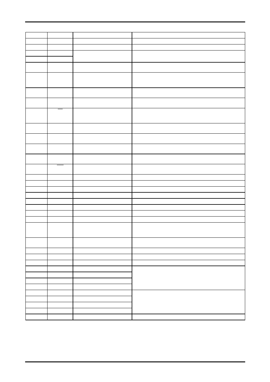
Pin Functions
Pin No.
Symbol
Type
Functional description
1
VSS1
Ground
Connect a ground to this pin. (Digital system ground)
2
VDD1
Power supply (+3.3V)
Digital system power supply: +3.3V
3
OSCin
4
OSCout
LC oscillator
Connect to the character output dot clock generator oscillator coil and
capacitor.
5
EXTclk
External clock signal input
Receives an external clock signal.
Capacitor coupling, 50% duty cycle, 0.5Vp-p or higher
6
CTRL1
OSCin oscillator input control
Switches between external clock input mode and LC oscillator mode.
Low: LC oscillator, high: external clock input MORE+
OR control with MORE+ command
7
SCLK
Clock input
Clock input for the serial data input system
MORE+ (This input has hysteresis characteristics.)
8
SIN
Data input
Serial data input
MORE+ (This input has hysteresis characteristics.)
9
CS
Enable input
Enable input for the serial data input system. Serial data input is enabled
when this pin is set low.
MORE+ (This input has hysteresis characteristics.)
10
VSYNC
Vertical sync signal input
MORE+ (This input has hysteresis characteristics.)
11
HSYNC
Horizontal sync signal input
MORE+ (This input has hysteresis characteristics.)
12
TEST1
Test mode control 1
Low: normal operation, high: test mode MORE+
13
TEST2
Test mode control 2
Low: normal operation, high: test mode (scan mode) MORE+
14
RST
Reset input
System reset input
MORE+ (This input has hysteresis characteristics.)
15
CLKOUT
Clock output
16
VSS1
Ground
Connect a ground to this pin. (Digital system ground)
17
NC
18
NC
19
NC
20
NC
21
NC
22
VSS4
Ground
Connect a ground tro this pin. (PLL system power supply)
23
PD0
PLL charge pump output
PLL VCO control voltage input
Charge pump output
Connect a LPF (lug lead filter) to this pin.
Voltage input for internal VCO control
24
VCOR
VCO variable range adjustment
Used to adjust variable voltage range of internal VCO.
Connect a resistor to this pin.
25
VDD4
Power supply (+3.3V)
PLL system power supply: +3.3V
26
BFin
Amplifier input
Oscillation input for external VCO
27
BFout
Amplifier output
Oscillation output for external VCO
28
RD3
Rout output: bit 3
29
RD2
Rout output: bit 2
30
RD1
Rout output: bit 1
31
RD0
Rout output: bit 0
Rout output
This is a 4-bit digital output with values from 0000 to 1111.
32
GD3
Gout output: bit 3
33
GD2
Gout output: bit 2
34
GD1
Gout output: bit 1
35
GD0
Gout output: bit 0
Gout output
This is a 4-bit digital output with values from 0000 to 1111.
36
VDD1
Power supply (+3.3V)
Digital system power supply: +3.3V
Continued on next page.
相關(guān)PDF資料 |
PDF描述 |
|---|---|
| LC74751 | ON-SCREEN DISPLAY IC, PDIP22 |
| LC7475 | ON-SCREEN DISPLAY IC, PDIP22 |
| LC74760 | ON-SCREEN DISPLAY IC, PDIP30 |
| LC74760M | ON-SCREEN DISPLAY IC, PDSO30 |
| LC74761 | ON-SCREEN DISPLAY IC, PDIP30 |
相關(guān)代理商/技術(shù)參數(shù) |
參數(shù)描述 |
|---|---|
| LC74736PT_11 | 制造商:SANYO 制造商全稱:Sanyo Semicon Device 功能描述:On-Screen Display Controller |
| LC74736PT-E | 功能描述:顯示驅(qū)動(dòng)器和控制器 RoHS:否 制造商:Panasonic Electronic Components 工作電源電壓:2.7 V to 5.5 V 最大工作溫度: 安裝風(fēng)格:SMD/SMT 封裝 / 箱體:QFN-44 封裝:Reel |
| LC7475 | 制造商:SANYO 制造商全稱:Sanyo Semicon Device 功能描述:On-screen Display Controller for PAL-format Video |
| LC74751 | 制造商:SANYO 制造商全稱:Sanyo Semicon Device 功能描述:On-Screen Display LSI |
| LC74759JM-9820-TRM-E | 制造商:SANYO Semiconductor Co Ltd 功能描述:ELECTRONIC COMPONENT |
發(fā)布緊急采購(gòu),3分鐘左右您將得到回復(fù)。