- 您現在的位置:買賣IC網 > PDF目錄30736 > LC78605E SPECIALTY CONSUMER CIRCUIT, PQFP64 PDF資料下載
參數資料
| 型號: | LC78605E |
| 元件分類: | 消費家電 |
| 英文描述: | SPECIALTY CONSUMER CIRCUIT, PQFP64 |
| 封裝: | 14 X 14 MM, QIP-64 |
| 文件頁數: | 10/11頁 |
| 文件大小: | 94K |
| 代理商: | LC78605E |
No.7735-8/11
LC78605E
Continued from preceding page.
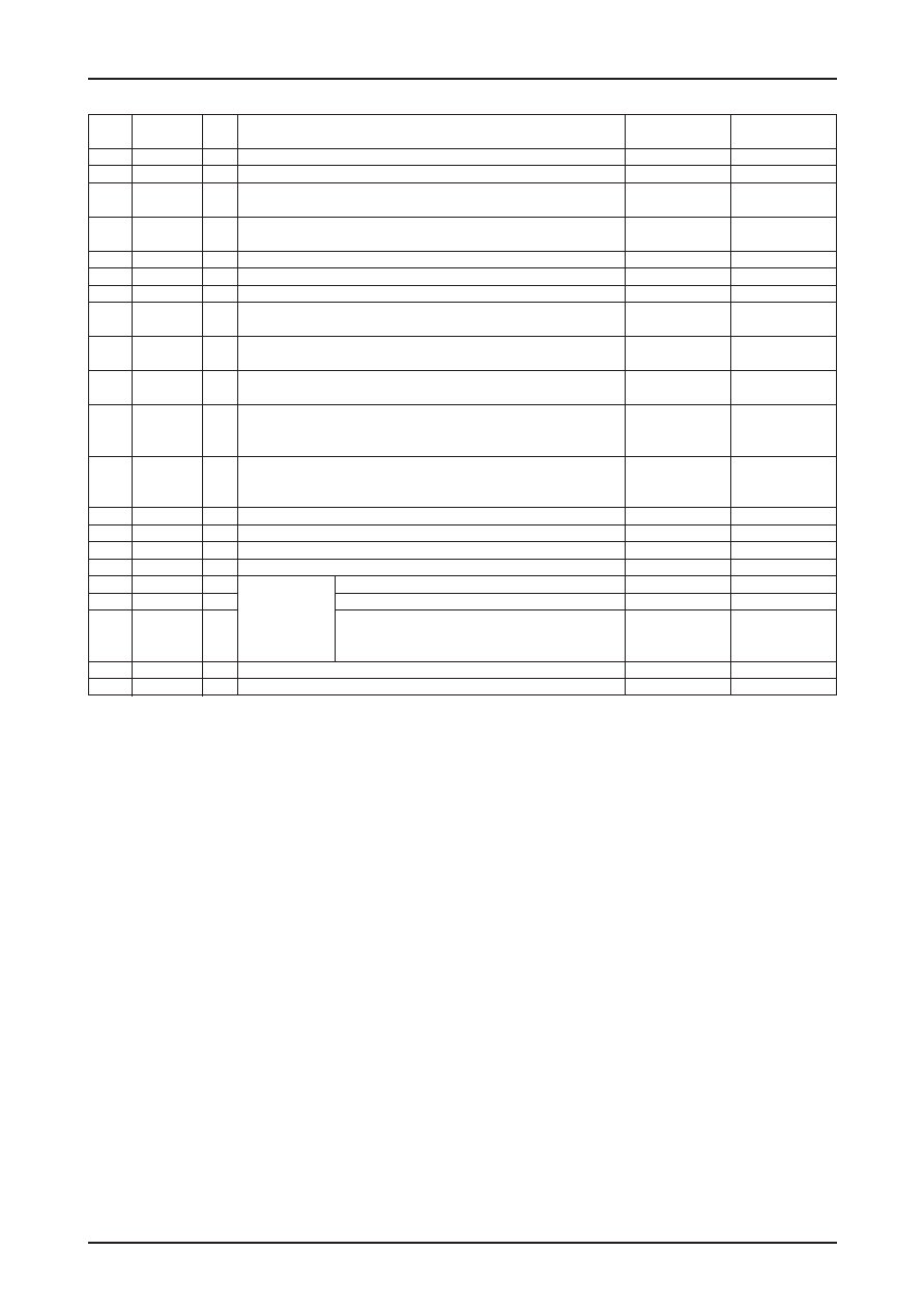
Pin No.
Pin Name
I/O
Function
Pin state when
CDRESB is low
TUNERESB is low
44
FMAMB
I
Tuner display switching selection input (Schmitt trigger input)
—
45
REMOTE
I
Remote control signal input (Schmitt trigger input)
—
46
CLOSE
I
Close switch detection signal input.
—
A pull-up resistor is built in. (Schmitt trigger input)
47
PUIN
I
Limit switch detection signal input.
—
A pull-up resistor is built in. (Schmitt trigger input)
48
DVSS
—
Digital system ground. This pin must be connected to the 0 V level.
—
49
DVDD
—
Digital system 3.3V power supply
—
50
TUNERIN
I
Tuner frequency display input
—
51
MONI3
I/O
Internal signal monitor pin 3. (Schmitt trigger input)
(Low-level output)
Undefined
A pull-down resistor is built in. (Default: input mode)
52
MONI2
I/O
Internal signal monitor pin 2. (Schmitt trigger input)
(Low-level output)
Undefined
A pull-down resistor is built in. (Default: input mode)
53
MONI1
I/O
Internal signal monitor pin 1. (Schmitt trigger input)
(Low-level output)
Undefined
A pull-down resistor is built in. (Default: input mode)
Reset input for this IC’s tuner display block.
54
TUNERESB
I
A pull-down resistor is built in.
—
This pin must be set low briefly after power is first applied.
Reset input for this IC’s CD playback block.
55
CDRESB
I
A pull-down resistor is built in.
—
This pin must be set low briefly after power is first applied.
56
AD1
AI
Key operation A/D converter input 1
—
57
AD2
AI
Key operation A/D converter input 2
—
58
AD3
AI
Key operation A/D converter input 3
—
59
AVSS
—
Analog system ground. This pin must be connected to the 0V level.
—
60
PDO
AO
External VCO control phase comparator output
Undefined
61
ISET
AI
PDO output current adjustment resistor connection
—
PLL system pins
VCO frequency range adjustment
62
FR
AI
An external resistor must be connected between this pin
—
and AVDD.
63
AVDD
—
Analog system power supply
—
64
SLCO
AO
Slice level control output
Undefined
相關PDF資料 |
PDF描述 |
|---|---|
| LC7861KE | SPECIALTY CONSUMER CIRCUIT, PQFP64 |
| LC78625E | SPECIALTY CONSUMER CIRCUIT, PQFP80 |
| LC78630E | SPECIALTY CONSUMER CIRCUIT, PQFP80 |
| LC78631E | SPECIALTY CONSUMER CIRCUIT, PQFP80 |
| LC78637E | SPECIALTY CONSUMER CIRCUIT, PQFP80 |
相關代理商/技術參數 |
參數描述 |
|---|---|
| LC7860KA | 制造商:SANYO 制造商全稱:Sanyo Semicon Device 功能描述:DIGITAL SIGNAL PROCESSOR FOR COMPACT DISC PLAYERS |
| LC7860N | 制造商:SANYO 制造商全稱:Sanyo Semicon Device 功能描述:DIGITAL SIGNAL PROCESSOR FOR COMPACT DISC PLAYERS |
| LC7861KE | 制造商:SANYO 制造商全稱:Sanyo Semicon Device 功能描述:Digital Signal Processor for Compact Disc Players |
| LC78620E | 制造商:SANYO 制造商全稱:Sanyo Semicon Device 功能描述:Compact Disc Player DSP |
| LC78621E | 制造商:SANYO 制造商全稱:Sanyo Semicon Device 功能描述:Compact Disc Player DSP |
發布緊急采購,3分鐘左右您將得到回復。