- 您現(xiàn)在的位置:買賣IC網(wǎng) > PDF目錄367560 > LKP1AF-24V PDF資料下載
參數(shù)資料
| 型號: | LKP1AF-24V |
| 文件頁數(shù): | 1/3頁 |
| 文件大小: | 45K |
| 代理商: | LKP1AF-24V |
LK-P
56
LK-P
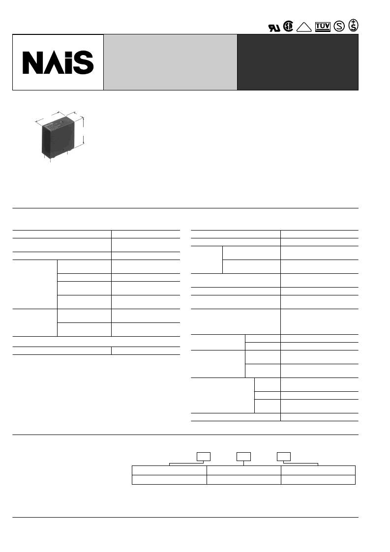
RELAYS
10 A Slim Power Relay
mm
inch
25.0
.984
24.0
.945
11.0
.433
FEATURES
1. High switching capacity: 10 A 277V AC
2. High insulation resistance between
contact and coil
1) Creepage distance and clearances
between contact and coil: Min. 6 mm .
236
inch
(In compliance with IEC65)
2) Surge withstand voltage between contact
and coil: 10,000 V or more
3. High noise immunity realized by the
card separation structure between con-
tact and coil
4. Popular terminal pitch in AV equip-
ment field
5. Space-saving slim type
Base area: Width 11
Width .433
6. Conforms to the various safety stan-
dards
UL/CSA, VDE, TüV and SEMKO, SEV
approved
×
Length 24 mm
×
Length .945 inch
SPECIFICATIONS
Contact
Arrangement
Initial contact resistance, max.
(By voltage drop 6 V DC 1 A)
Contact material
Coil
Nominal operating power
Remarks
* Specifications will vary with foreign standards certification ratings.
*
Measurement at same location as "Initial breakdown voltage" section.
*
Detection current: 10mA
*
Wave is standard shock voltage of
*
Excluding contact bounce time.
*
Half-wave pulse of sine wave: 11 ms; detection time: 10
*
Half-wave pulse of sine wave: 6 ms
*
Detection time: 10
μ
s
*
Refer to 5. Conditions for operation, transport and storage mentioned in
AMBIENT ENVIRONMENT (Page 24).
1
2
3
±
1.2
×
50
μ
s according to JEC-212-1981
4
5
μ
s
6
7
8
Characteristics
Max. operating speed
Initial insulation resistance*
1 Form A
Max. 100 m
Silver alloy
Rating
(resistive load)
Nominal switching
capacity
Max. switching power
Max. switching
voltage
Max. switching
current
Mechanical
(at 180 cpm)
Electrical (at 20 cpm)
(at rated load)
10 A 277 V AC, 5 A 30V DC
2,770 V A, 150W
277 V AC, 30 V DC
10 A (AC), 5A (DC)
Expected life
(min. operations)
2
×
10
6
10
5
530 mW
20 cpm (at rated load)
Min. 1,000 M
1
(at 500 V DC)
Initial *
breakdown
voltage
2
Between open
contacts
Between contact and
coil
1,000 Vrms for 1 min.
4,000 Vrms for 1 min.
Initial surge voltage between contact
and coil*
Operate time*
(at nominal voltage)
Release time (without diode)*
(at nominal voltage)
3
Min. 10,000 V
4
Approx. 7 ms (at 20
°
C
68
°
F
)
4
Approx. 2 ms (at 20
°
C
68
°
F
)
Temperature rise (at 70
°
C)
Max. 45
voltage and at 10 A contact
carrying current
(resistance method)
Min. 200 m/s
{approx. 20 G}
Min. 1,000 m/s
10 to 55Hz
at double amplitude of 1.5mm
10 to 55Hz
at double amplitude of 1.5mm
–40
°
C to +70
–40
°
F to +158
5 to 85% R.H.
°
C with nominal coil
Shock resistance
Functional*
Destructive*
5
2
6
2
{approx. 100 G}
Vibration resistance
Functional*
7
Destructive
Conditions for operation,
transport and storage*
(Not freezing and con-
densing at low tempera-
ture)
8
Ambient
temp.
Humidity
Air
pressure
°
C
°
F
86 to 106 kPa
Unit weight
Approx. 12 g
.42 oz
TYPICAL
APPLICATIONS
Audio visual equipment
TVs, VTRs
Office equipment
LBP, CRT
Home appliances
Refrigerator, Air conditioner
ORDERING INFORMATION
Contact arrangement
1a: 1 Form A
Protective construction
F: Flux-resistant type
Coil voltage(DC)
12, 24V
UL/CSA, TüV, SEMKO, TV-5 approved type is standard.
Notes 1. Standard packing Carton: 100 pcs. Case: 500 pcs.
2. 5 V, 9 V, 18 V DC types are also available. Please consult us for details.
Ex. LKP
1a
F
12V
–
VDE
相關PDF資料 |
PDF描述 |
|---|---|
| LKP5660-6R | 250 Watt AC-DC Converters |
| LKP5661-5R | 250 Watt AC-DC Converters |
| LKP5662-7R | 250 Watt AC-DC Converters |
| LKP5740-6R | 250 Watt AC-DC Converters |
| LKP5741-5R | 250 Watt AC-DC Converters |
相關代理商/技術參數(shù) |
參數(shù)描述 |
|---|---|
| LKP1AF-24V-T | 制造商:Panasonic Electric Works 功能描述:RELAY PCB SPNO 10A 24VDC 制造商:Panasonic Electric Works 功能描述:RELAY, PCB, SPNO, 10A, 24VDC |
| LKP1AF5 | 制造商:Panasonic Electric Works 功能描述:PCB slim relay,SPNO,flux proof,10A 5Vdc |
| LKP1AF5T | 制造商:Panasonic Electric Works 功能描述: |
| LKP1AF-5V | 功能描述:通用繼電器 1 Form A 10A 277VAC 5A 30VDC 5V RoHS:否 制造商:Omron Electronics 觸點形式:1 Form A (SPST-NO) 觸點電流額定值:150 A 線圈電壓:24 VDC 線圈電阻:144 Ohms 線圈電流:167 mA 切換電壓:400 V 安裝風格:Chassis 觸點材料: |
| LKP1AF-6V | 功能描述:通用繼電器 1 Form A 10A 277VAC 5A 30VDC 6V RoHS:否 制造商:Omron Electronics 觸點形式:1 Form A (SPST-NO) 觸點電流額定值:150 A 線圈電壓:24 VDC 線圈電阻:144 Ohms 線圈電流:167 mA 切換電壓:400 V 安裝風格:Chassis 觸點材料: |
發(fā)布緊急采購,3分鐘左右您將得到回復。