- 您現在的位置:買賣IC網 > PDF目錄30743 > LM1269NA/NOPB (NATIONAL SEMICONDUCTOR CORP) 3 CHANNEL, VIDEO PREAMPLIFIER, PDIP24 PDF資料下載
參數資料
| 型號: | LM1269NA/NOPB |
| 廠商: | NATIONAL SEMICONDUCTOR CORP |
| 元件分類: | 音頻/視頻放大 |
| 英文描述: | 3 CHANNEL, VIDEO PREAMPLIFIER, PDIP24 |
| 封裝: | PLASTIC, DIP-24 |
| 文件頁數: | 11/20頁 |
| 文件大小: | 1676K |
| 代理商: | LM1269NA/NOPB |
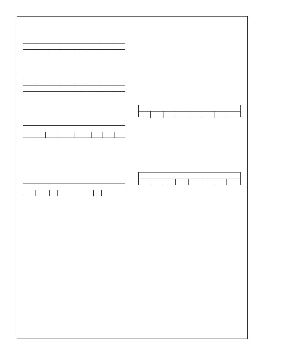
DAC Interface Register Definitions
(Continued)
Bit 7
Bit 0
D3–7 D3–6 D3–5 D3–4 D3–3 D3–2 D3–1 D3–0
Bits 7–0: DAC 3. These eight bits determine the output
voltage of DAC 3.
DAC 4 Register (I
2C address 07h)
Register name: DAC 4 (07h)
Bit 7
Bit 0
D4–7 D4–6 D4–5 D4–4 D4–3 D4–2 D4–1 D4–0
Bits 7–0: DAC 4. These eight bits determine the output
voltage of DAC 4.
DC Offset and OSD Contrast Control Register (I
2C ad-
dress 08h)
Register name: DC Offset/OSD Cont. (08h)
Bit 7
Bit 0
RSV
OSDC1
OSDC0
DC2
DC1
DC0
Bits 2–0: DC Offset Control. These three bits determine the
active video DC offset to all three channels.
Bits 4–3: OSD Contrast Control. These two bits determine
the contrast level of the OSD information.
Bits 7–5: Reserved.
Global Video Control Register (I
2C address 09h)
Register name: Global Control (09h)
Bit 7
Bit 0
RSV
0
DCF4
DCF1–3
0
PS
BV
Bit 0:
Blank Video. When this bit is a one, blank the
video output. When this bit is a zero allow normal
video out.
Bit 1:
Power Save. When this bit is a one, shut down
the analog circuits to support sleep mode. When
this bit is a zero enable the analog circuits for
normal operation.
Bit 2:
MUST BE SET TO “0” FOR PROPER OPERA-
TION.
Bit 3:
DAC1–3 Configuration. When this bit is a zero
the DAC outputs of DAC1–3 are full scale
(0V–4.5V). When this bit is 1, the range of
DAC1–3 are halved (0V–2.25V).
Bit 4:
DAC4 Configuration. When this bit is a zero the
DAC4 output is not mixed with the other DAC
outputs. When the bit is one, 50% of the DAC4
output is added to DAC1–3.
Bit 5:
MUST BE SET TO “0” FOR PROPER OPERA-
TION.
Bits 7–6: Reserved.
Increment Mode Register (I
2C address 0Ah)
Register name: Increment Mode (0Ah)
Bit 7
Bit 0
RSV
TST
INCR
Bit 0:
Increment Enable. When set to a “0”, the default
value, the increment mode is enabled. This al-
lows the registers to be updated sequentially by
sending another block of data.
Bit 1:
MUST BE SET TO “0” FOR PROPER OPERA-
TION.
Bits 7–2: Reserved.
Software Reset Register (I
2C address 0Fh)
Register name: Software Reset (0Fh)
Bit 7
Bit 0
RSV
SRST
Bit 0:
Software Reset. Setting this bit causes a software
reset. All registers (except this one) are loaded
with their default values. All operations currently
in progress are aborted (except for I
2C transac-
tions). This bit automatically clears itself when the
reset has been completed.
Bits 7–1: Reserved.
LM1269
www.national.com
19
相關PDF資料 |
PDF描述 |
|---|---|
| LM1276AAA/NA | 1 CHANNEL, VIDEO PREAMPLIFIER, PDIP28 |
| LM1279AN/NOPB | 3 CHANNEL, VIDEO AMPLIFIER, PDIP20 |
| LM1279N/NOPB | 1 CHANNEL, VIDEO AMPLIFIER, PDIP20 |
| LM136A-2.5MD8 | 1-OUTPUT TWO TERM VOLTAGE REFERENCE, 5 V, UUC |
| LM136A-5.0MW8 | 1-OUTPUT TWO TERM VOLTAGE REFERENCE, 5 V, UUC |
相關代理商/技術參數 |
參數描述 |
|---|---|
| LM126H | 制造商:NSC 制造商全稱:National Semiconductor 功能描述:VOLTAGE REGULATORS |
| LM126H/883B | 制造商:Texas Instruments 功能描述:IC,VOLT REGULATOR,FIXED,+-12V,BIPOLAR,CAN,10PIN,METAL |
| LM126H/883C | 制造商:Texas Instruments 功能描述: |
| LM1270 | 制造商:NSC 制造商全稱:National Semiconductor 功能描述:Hi-Brite 200 MHz I2C Compatible RGB Image Enhancer with Video Auto Sizing |
| LM1270N | 制造商:NSC 制造商全稱:National Semiconductor 功能描述:Hi-Brite 200 MHz I2C Compatible RGB Image Enhancer with Video Auto Sizing |
發布緊急采購,3分鐘左右您將得到回復。