- 您現在的位置:買賣IC網 > PDF目錄361028 > LM3916N (NATIONAL SEMICONDUCTOR CORP) Dot/Bar Display Driver PDF資料下載
參數資料
| 型號: | LM3916N |
| 廠商: | NATIONAL SEMICONDUCTOR CORP |
| 元件分類: | 顯示驅動器 |
| 英文描述: | Dot/Bar Display Driver |
| 中文描述: | LED DISPLAY DRIVER, PDIP18 |
| 封裝: | PLASTIC, DIP-18 |
| 文件頁數: | 10/27頁 |
| 文件大小: | 509K |
| 代理商: | LM3916N |
第1頁第2頁第3頁第4頁第5頁第6頁第7頁第8頁第9頁當前第10頁第11頁第12頁第13頁第14頁第15頁第16頁第17頁第18頁第19頁第20頁第21頁第22頁第23頁第24頁第25頁第26頁第27頁
Application Hints
(Continued)
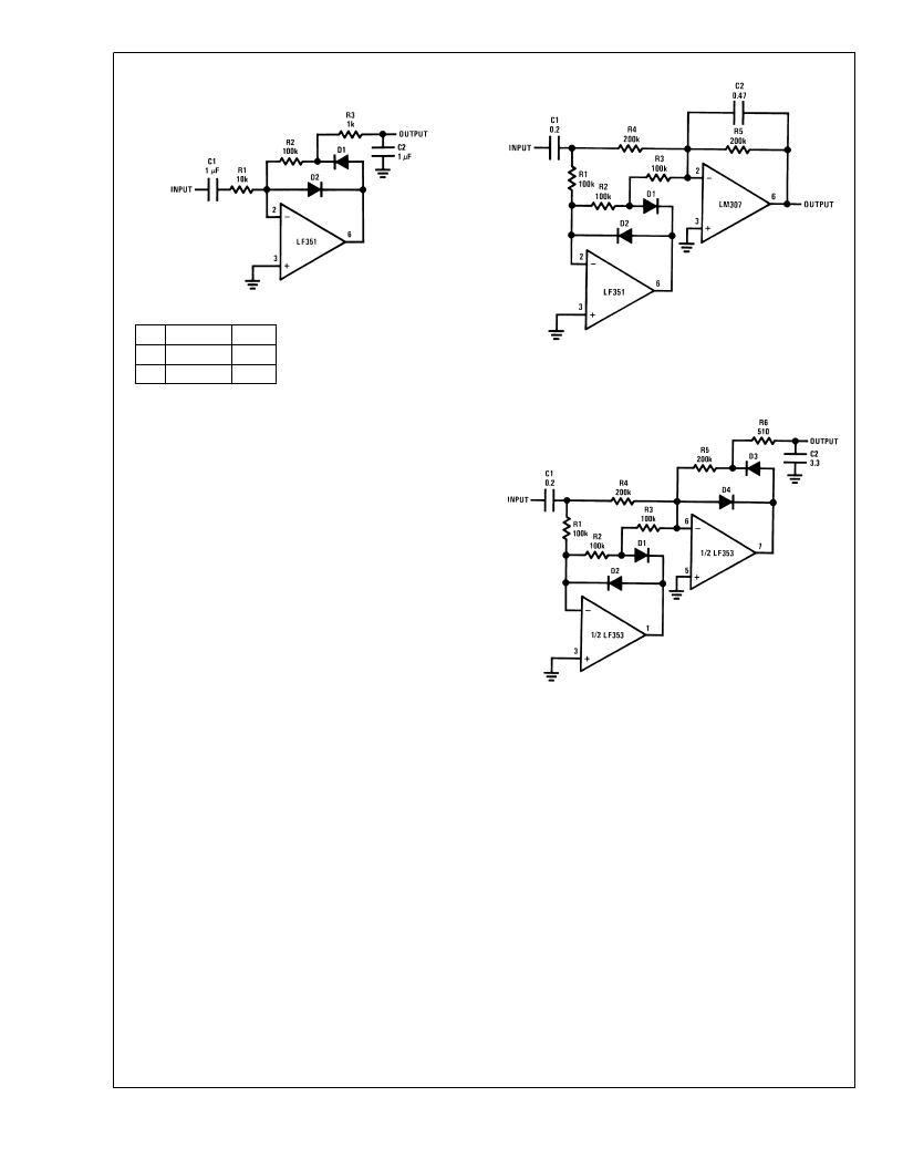
For precision full-wave averaging use the circuit in Figure 5
Using 1% resistors for R1 through R4, gain for positive and
negative signal differs by only 0.5 dB worst case. Substitut-
ing 5% resistors increases this to 2 dB worst case. (A 2 dB
gain difference means that the display may have a
±
1 dB er-
ror when the input is a nonsymmetrical transient). The aver-
aging time constant is R5
C2. A simple modification results
in the precision full-wave detector of Figure 6 Since the filter
capacitor is not buffered, this circuit can drive only high im-
pedance loads such as the input of an LM3916.
AUDIO METER STANDARDS
VU Meter
The audio level meter most frequently encountered is the VU
meter. Its characteristics are defined as the ANSI specifica-
tion C165. The LM3916’s outputs correspond to the meter
indications specified with the omission of the 2 VU indica-
tion. The VU scale divisions differ slightly from a linear scale
in order to obtain whole numbers in dB.
Some of the most important specifications for an AC meter
are its dynamic characteristics. These define how the meter
responds to transients and how fast the reading decays. The
VU meter is a relatively slow full-wave averaging type, speci-
fied to reach 99% deflection in 300 ms and overshoot by 1 to
1.5%. In engineering terms this means a slightly under-
damped second order response with a resonant frequency
of 2.1 Hz and a Q of 0.62. Figure 7 depicts a simple rectifier/
filter circuit that meets these criteria.
DS007971-11
D1, D2: 1N914 or 1N4148
Average
1k
100k
Peak
100k
1k
R2
R3
R1 = R2 for A
= 1
R1 = R2/10 for A
V
= 10
C1 = 10/R1
FIGURE 4. Precision Half-Wave Rectifier
DS007971-12
D1, D2: 1N914 or 1N4148
FIGURE 5. Precision Full-Wave Average Detector
DS007971-13
D1, D2, D3, D4: 1N914 OR 1N4148
Attack and decay time to DIN PPM spec. Response down 1 dB for 10 ms
tone burst. Decays 20 dB in 1.5s.
FIGURE 6. Precision Full-Wave Peak Detector
L
www.national.com
10
相關PDF資料 |
PDF描述 |
|---|---|
| LM3916N-1 | 6 PIN MINI DIN CABLE MM 50FT |
| LM395 | Ultra Reliable Power Transistors |
| LM395T | Ultra Reliable Power Transistors |
| LM399 | Precision Reference |
| LM3999Z | IC-6.95V PRECISION REFERENCE |
相關代理商/技術參數 |
參數描述 |
|---|---|
| LM3916N/A+ | 制造商:未知廠家 制造商全稱:未知廠家 功能描述:Vacuum Fluorescent Display Driver |
| LM3916N/B+ | 制造商:未知廠家 制造商全稱:未知廠家 功能描述:Vacuum Fluorescent Display Driver |
| LM3916N1 | 制造商:National Semiconductor 功能描述:LED DRVR 10Segment 3.3V/5V/9V/12V/15V/18V/24V 18-Pin PDIP Tube |
| LM3916N-1 | 功能描述:LED照明驅動器 RoHS:否 制造商:STMicroelectronics 輸入電壓:11.5 V to 23 V 工作頻率: 最大電源電流:1.7 mA 輸出電流: 最大工作溫度: 安裝風格:SMD/SMT 封裝 / 箱體:SO-16N |
| LM3916N-1 | 制造商:Texas Instruments 功能描述:LED BAR GRAPH DRIVER 3916 DIP18 |
發布緊急采購,3分鐘左右您將得到回復。