- 您現在的位置:買賣IC網 > PDF目錄361030 > LM5030 (National Semiconductor Corporation) 100V Push-Pull Current Mode PWM Controller PDF資料下載
參數資料
| 型號: | LM5030 |
| 廠商: | National Semiconductor Corporation |
| 英文描述: | 100V Push-Pull Current Mode PWM Controller |
| 中文描述: | 100V的推挽式電流模式PWM控制器 |
| 文件頁數: | 5/11頁 |
| 文件大小: | 230K |
| 代理商: | LM5030 |
Electrical Characteristics
(Continued)
Specifications in standard type face are for T
J
= +25C and those in
boldface type
apply over the full operating junction tem-
perature range. Unless otherwise specified: V
IN
= 48V, V
CC
= 10V, and RT = 26.7K
Symbol
Parameter
Conditions
Min
(Note 4)
Typ
(Note 5)
Max
(Note 4)
Units
Oscillator
Frequency1 (RT = 26.7K)
Frequency2 (RT = 8.2K)
Sync threshold
175
510
200
600
3.2
225
690
3.8
kHz
kHz
V
PWM Comparator
Delay to Output
COMP set to 2V CS
stepped 0 to 0.4V, Time
to onset of OUT transition
low
Inferred from deadtime
COMP=0V
30
ns
Max Duty Cycle
Min Duty Cycle
COMP to PWM Comparator
Gain
COMP Open Circuit Voltage
COMP Short Circuit Current
Slope Compensation
Slope Comp Amplitude
47.5
49
50
0
%
%
0.34
V
FB
= 0V
V
FB
= 0V, COMP=0V
4.3
0.6
5.2
1.1
6.1
1.5
V
mA
Delta increase at PWM
Comparator to CS
80
105
130
mV
Output Section
Deadtime
Output High Saturation
Output Low Saturation
Rise Time
Fall Time
Cload = 0, 10% to 10%
Iout = 50mA, V
CC
- V
OUT
I
OUT
= 100mA
Cload = 1nF
Cload = 1nF
85
135
0.25
0.25
16
16
185
0.75
0.75
ns
V
V
ns
ns
Thermal Shutdown
Tsd
Thermal Shutdown Temp.
Thermal Shutdown Hysteresis
165
15
C
C
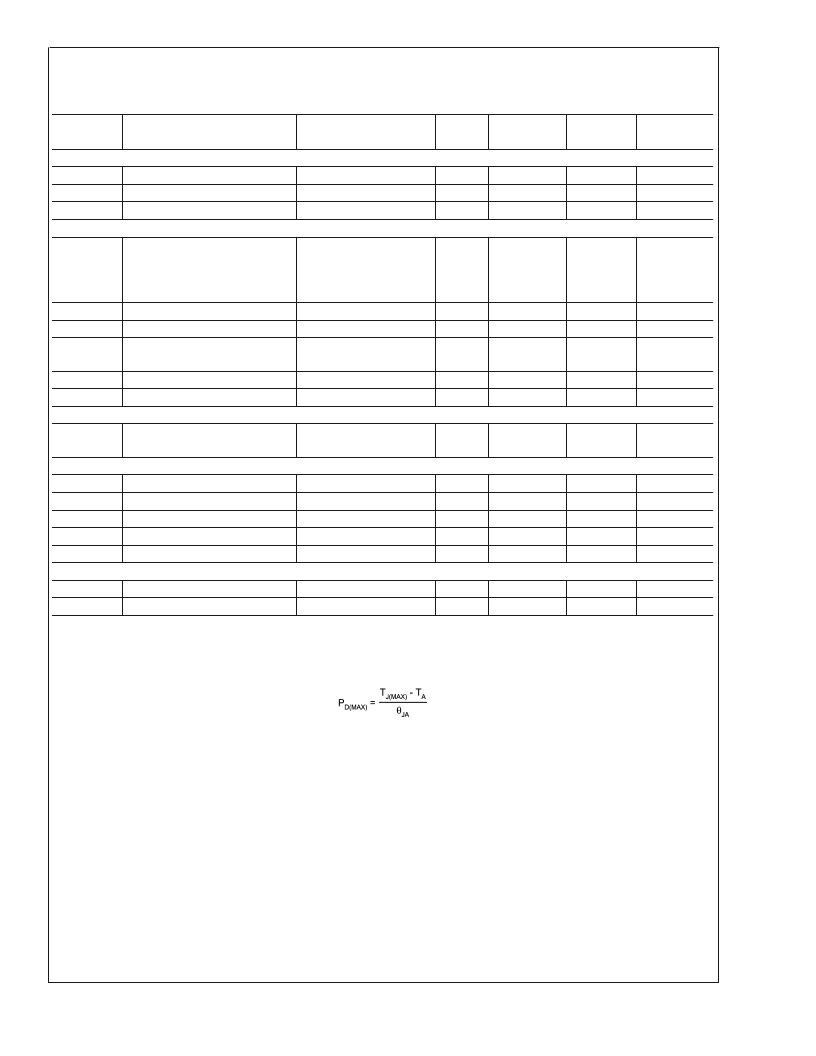
Note 1:
Absolute Maximum Ratings are limits beyond which damage to the device may occur. Operating Ratings are conditions under which operation of the device
is intended to be functional. For guaranteed specifications and test conditions, see the Electrical Characteristics.
Note 2:
The maximum allowable power dissipation is a function of the maximum junction temperature, T
J(MAX)
, the junction-to-ambient thermal resistance,
θ
JA
, and
the ambient temperature, T
A
. The maximum allowable power dissipation at any ambient temperture is calculated using:
Where the value of
θ
JA
for the mini SO-10 (MM) package is 200C/W. Exceeding the maximum allowable dissipation will cause excessive die temperature, and the
device will go into thermal shutdown.
Note 3:
The human body model is a 100pF capacitor discharged through a 1.5k
resistor into each pin. The machine model is a 200pF capacitor discharged directly
into each pin. The machine model ESD rating for pin 5 and pin 6 is 150V.
Note 4:
Limits are 100% production tested at 25C. Limits over the operating temperature range are guaranteed through correlation using Statistical Quality Control
(SQC) methods. The limits are used to calculate National’s Average Outgoing Quality Level (AOQL).
Note 5:
Typical numbers represent the most likely parametric norm for 25C operation.
L
www.national.com
5
相關PDF資料 |
PDF描述 |
|---|---|
| LM5030MM | 100V Push-Pull Current Mode PWM Controller |
| LM5030MMX | 100V Push-Pull Current Mode PWM Controller |
| LM556 | Dual Timer |
| LM556ICN | Analog Timer Circuit |
| LM556J-MIL | Analog Timer Circuit |
相關代理商/技術參數 |
參數描述 |
|---|---|
| LM5030_05 | 制造商:NSC 制造商全稱:National Semiconductor 功能描述:100V Push-Pull Current Mode PWM Controller |
| LM5030EVAL | 功能描述:電源管理IC開發工具 LM5030 EVAL BOARD RoHS:否 制造商:Maxim Integrated 產品:Evaluation Kits 類型:Battery Management 工具用于評估:MAX17710GB 輸入電壓: 輸出電壓:1.8 V |
| LM5030MM | 功能描述:電流型 PWM 控制器 RoHS:否 制造商:Texas Instruments 開關頻率:27 KHz 上升時間: 下降時間: 工作電源電壓:6 V to 15 V 工作電源電流:1.5 mA 輸出端數量:1 最大工作溫度:+ 105 C 安裝風格:SMD/SMT 封裝 / 箱體:TSSOP-14 |
| LM5030MM | 制造商:Texas Instruments 功能描述:IC SW REG POWERWISE MSOP10 |
| LM5030MM/NOPB | 功能描述:電流型 PWM 控制器 100V Push-Pull Curr Mode PWM Controller RoHS:否 制造商:Texas Instruments 開關頻率:27 KHz 上升時間: 下降時間: 工作電源電壓:6 V to 15 V 工作電源電流:1.5 mA 輸出端數量:1 最大工作溫度:+ 105 C 安裝風格:SMD/SMT 封裝 / 箱體:TSSOP-14 |
發布緊急采購,3分鐘左右您將得到回復。