- 您現在的位置:買賣IC網 > PDF目錄361031 > LM6181 (National Semiconductor Corporation) 100 mA, 100 MHz Current Feedback Amplifier PDF資料下載
參數資料
| 型號: | LM6181 |
| 廠商: | National Semiconductor Corporation |
| 英文描述: | 100 mA, 100 MHz Current Feedback Amplifier |
| 中文描述: | 一〇 〇毫安,100 MHz電流反饋放大器 |
| 文件頁數: | 4/23頁 |
| 文件大小: | 1848K |
| 代理商: | LM6181 |
±
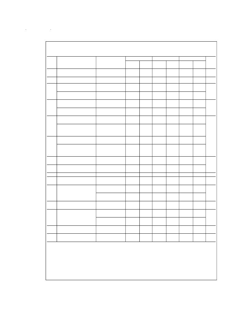
5V DC Electrical Characteristics
The following specifications apply for Supply Voltage =
±
5V, R
= 820
, and R
L
= 1 k
unless otherwise noted.
Boldface
limits apply at the temperature extremes; all other limits T
J
= 25C.
Symbol
Parameter
Conditions
LM6181AM
Typical
(Note 4)
1.0
LM6181AI
Typical
(Note 4)
1.0
LM6181I
Units
Limit
(Note 5)
2.0
3.0
Limit
(Note 5)
2.0
2.5
Typical
(Note 4)
1.0
Limit
(Note 5)
3.0
3.5
V
OS
Input Offset Voltage
mV
max
μV/C
TC
V
OS
I
B
Input Offset Voltage Drift
2.5
2.5
2.5
Inverting Input
Bias Current
Non-Inverting Input
Bias Current
Inverting Input Bias
Current Drift
Non-Inverting Input
Bias Current Drift
Inverting Input Bias Current
Power Supply Rejection
Non-Inverting Input
Bias Current
Power Supply Rejection
Inverting Input Bias Current
Common Mode Rejection
Non-Inverting Input
Bias Current
Common Mode Rejection
Common Mode
Rejection Ratio
Power Supply
Rejection Ratio
Output Resistance
Non-Inverting
Input Resistance
Output Voltage Swing
5.0
10
22
1.5
1.5
5.0
10
22
1.5
1.5
5.0
17.5
27.0
3.0
5.0
μA
max
0.25
0.25
0.25
TC I
B
50
50
50
nA/C
3.0
3.0
3.0
I
B
PSR
V
S
=
±
4.0V,
±
6.0V
0.3
0.5
0.5
0.5
0.3
0.5
0.5
0.5
0.3
1.0
1.0
0.5
μA/V
max
V
S
=
±
4.0V,
±
6.0V
0.05
0.05
0.05
0.5
0.5
1.0
0.5
0.5
0.5
1.0
0.5
0.5
1.0
1.5
0.5
I
B
CMR
2.5V
≤
V
CM
≤
+2.5V
0.3
0.3
0.3
2.5V
≤
V
CM
≤
+2.5V
0.12
0.12
0.12
1.0
50
47
70
70
0.5
50
47
70
70
0.5
50
47
64
64
CMRR
2.5V
≤
V
CM
≤
+2.5V
57
57
57
dB
min
PSRR
V
S
=
±
4.0V,
±
6.0V
80
80
80
R
O
R
IN
A
V
= 1, f = 300 kHz
0.25
8
0.25
8
0.25
8
M
min
V
min
V
O
R
L
= 1 k
2.6
2.25
2.2
2.0
2.0
75
70
0.75
0.35
0.5
0.25
8.5
8.5
2.6
2.25
2.25
2.0
2.0
75
70
0.75
0.4
0.5
0.25
8.5
8.5
2.6
2.25
2.25
2.0
2.0
75
70
0.6
0.3
0.4
0.2
8.5
8.5
R
L
= 100
2.2
2.2
2.2
I
SC
Output Short
Circuit Current
Transimpedance
100
100
100
mA
min
Z
T
R
L
= 1 k
1.4
1.4
1.0
M
min
R
L
= 100
1.0
1.0
1.0
I
S
Supply Current
No Load, V
O
= 0V
6.5
6.5
6.5
mA
max
V
V
CM
Input Common Mode
Voltage Range
V
+
1.7V
V
+ 1.7V
V
+
1.7V
V
+ 1.7V
V
+
1.7V
V
+ 1.7V
www.national.com
4
相關PDF資料 |
PDF描述 |
|---|---|
| LM6181AIM | 100 mA, 100 MHz Current Feedback Amplifier |
| LM6181AIM-8 | JT 79C 79#22D SKT WALL RECP |
| LM6181IM-8 | 100 mA, 100 MHz Current Feedback Amplifier |
| LM61 | 2.7V, SOT-23 or TO-92 Temperature Sensor |
| LM61CIM3X | 2.7V, SOT-23 or TO-92 Temperature Sensor |
相關代理商/技術參數 |
參數描述 |
|---|---|
| LM6181AIM | 制造商:Texas Instruments 功能描述: |
| LM6181AIM-8 | 制造商:Rochester Electronics LLC 功能描述:- Bulk |
| LM6181AIN | 制造商:NSC 制造商全稱:National Semiconductor 功能描述:100 mA, 100 MHz Current Feedback Amplifier |
| LM6181AJM | 制造商:Texas Instruments 功能描述: |
| LM6181AMJ/883 | 制造商:NSC 制造商全稱:National Semiconductor 功能描述:100 mA, 100 MHz Current Feedback Amplifier |
發布緊急采購,3分鐘左右您將得到回復。