- 您現在的位置:買賣IC網 > PDF目錄361034 > LM79 PDF資料下載
參數資料
| 型號: | LM79 |
| 文件頁數: | 17/31頁 |
| 文件大小: | 481K |
| 代理商: | LM79 |
第1頁第2頁第3頁第4頁第5頁第6頁第7頁第8頁第9頁第10頁第11頁第12頁第13頁第14頁第15頁第16頁當前第17頁第18頁第19頁第20頁第21頁第22頁第23頁第24頁第25頁第26頁第27頁第28頁第29頁第30頁第31頁
Functional Description
(Continued)
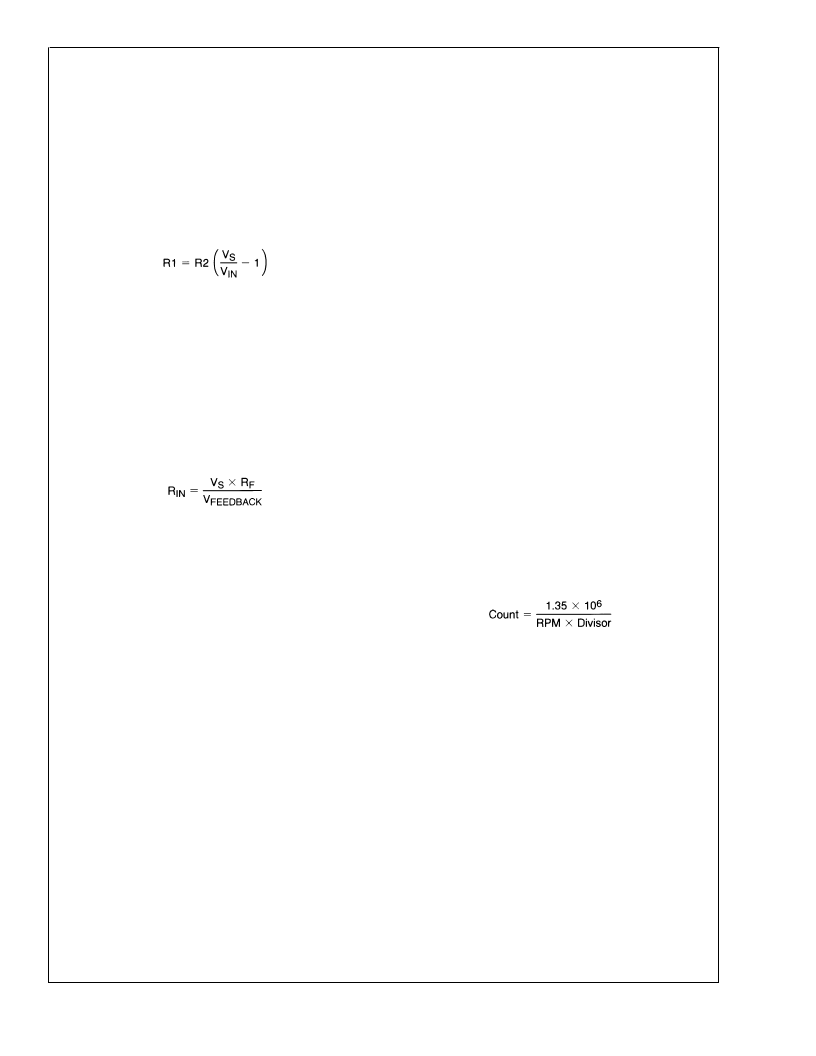
A typical application, such as is shown in Figure 8 might
select the input voltage divider to provide 3V at the analog
inputs of the LM79. This is sufficiently high for good resolu-
tion of the voltage, yet leaves headroom for upward excur-
sions from the supply of about 25%. To simplify the process
of resistor selection, set the value of R2 first. Select a value
for R2 between 10 k
and 100 k
. This is low enough to
avoid errors due to input leakage currents yet high enough to
both protect the inputs under overdrive conditions as well as
minimize loading of the source. Then select R1 to provide a
3V input according to:
The negative inputs provide inverting op amps with
non-inverting inputs connected to ground. The output of
these op amps are designed to only drive the input of the
LM78 and their associated feedback loops. Avoid heavy
loading, long lines, and capacitive loading with these op
amps. Additional loading may cause oscillations and thus
erroneous readings. The optimum feedback resistor (resistor
from Feedback to -IN pin) value is approximately 60 k
,
based on the op amp nominal output current rating of 50 μA
at an output voltage of 3V. Locate the feedback resistors as
close as possible to the LM79. The recommended range for
R
IN
is from 30 k
to 300 k
.
Select R
IN
according to:
The analog inputs have internal diodes that clamp inputs
exceeding the power supply and ground. Exceeding any
analog input has no detrimental effect on other channels.
The input diodes will also clamp voltages appearing at the
inputs of an un-powered LM79. External resistors should be
included to limit input currents to the values given in the
ABSOLUTE MAXIMUM RATINGS for Input Current At Any
Pin. Inputs with the attenuator networks will usually meet
these requirements. If it is possible for inputs without attenu-
ators (such as the 2.5V or 3.3V supplies) to be turned on
while LM79 is powered off, additional resistors of about 10
k
should be added in series with the inputs to limit the input
current.
5.0 LAYOUT AND GROUNDING
Analog inputs will provide best accuracy when referred to the
AGND pin. A separate, low-impedance ground plane for
analog ground, which provides a ground point for the voltage
dividers and analog components, will provide best perfor-
mance but is not mandatory. Analog components such as
voltage dividers and feedback resistors should be located
physically as close as possible to the LM79.
The power supply bypass, the parallel combination of 10 μF
(electrolytic or tantalum) and 0.1 μF (ceramic) bypass ca-
pacitors connected between pin 12 and ground, should also
be located as close as possible to the LM79.
6.0 FAN INPUTS
Inputs are provided for signals from fans equipped with
tachometer outputs. These are logic-level inputs with an
approximate threshold of 1.4V. Signal conditioning in the
LM79 accommodates the slow rise and fall times typical of
fan tachometer outputs. The maximum input signal range is
0 to V
. In the event these inputs are supplied from fan
outputs which exceed 0 to V
, either resistive division or
diode clamping must be included to keep inputs within an
acceptable range, as shown in Figure 9 R2 is selected so
that it does not develop excessive voltage due to input
leakage. R1 is selected based on R2 to provide a minimum
input of 2V and a maximum of V
. R1 should be as low as
possible to provide the maximum possible input up to V
for
best noise immunity. Alternatively, use a shunt reference or
zener diode to clamp the input level.
If fans can be powered while the power to the LM79 is off,
the LM79 inputs will provide diode clamping. Limit input
current to the Input Current at Any Pin specification shown in
the ABSOLUTE MAXIMUM RATINGS section. In most
cases, open collector outputs with pull-up resistors inher-
ently limit this current. If this maximum current could be
exceeded, either a larger pull up resistor should be used or
resistors connected in series with the fan inputs.
The Fan Inputs gate an internal 22.5 kHz oscillator for one
period of the Fan signal into an 8-bit counter (maximum
count = 255). The default divisor, located in the VID/Fan
Divisor Register, is set to 2 (choices are 1, 2, 4, and 8)
providing a nominal count of 153 for a 4400 rpm fan with two
pulses per revolution. Typical practice is to consider 70% of
normal RPM a fan failure, at which point the count will be
219.
Determine the fan count according to:
Note that Fan 1 and Fan 2 Divisors are programmable via
the VID/Fan Divisor Register. Fan 3 is not adjustable, and its
Divisor is always set to 2.
Fans that provide only one pulse per revolution would re-
quire a divisor set twice as high as fans that provide two
pulses, thus maintaining a nominal fan count of 153. There-
fore, the divisor should be set to 4 for a fan that provides 1
pulse per revolution with a nominal RPM of 4400.
L
www.national.com
17
相關PDF資料 |
PDF描述 |
|---|---|
| LM81CIMTX-32 | Serial Interface ACPI-Compatible Microprocessor System |
| LM81 | Serial Interface ACPI-Compatible Microprocessor System |
| LM81CIMT-31 | Serial Interface ACPI-Compatible Microprocessor System |
| LM82CIMQAX | Remote Diode and Local Digital Temperature Sensor with Two-Wire Interface |
| LM82CIMQA | Remote Diode and Local Digital Temperature Sensor with Two-Wire Interface |
相關代理商/技術參數 |
參數描述 |
|---|---|
| LM7900 | 制造商:未知廠家 制造商全稱:未知廠家 功能描述:3- TERMINAL NEGATIVE OUTPUT VOLTAGE REGULATORS |
| LM7900-220M | 制造商:SEME-LAB 制造商全稱:Seme LAB 功能描述:NEGATIVE VOLTAGE REGULATOR |
| LM7900-SMD | 制造商:SEME-LAB 制造商全稱:Seme LAB 功能描述:NEGATIVE VOLTAGE REGULATOR |
| LM7905 | 制造商:TGS 制造商全稱:Tiger Electronic Co.,Ltd 功能描述:3-Terminal 1A Positive Voltage Regulator |
| LM7905-220M | 制造商:未知廠家 制造商全稱:未知廠家 功能描述:Voltage Regulator |
發布緊急采購,3分鐘左右您將得到回復。