- 您現在的位置:買賣IC網 > PDF目錄361036 > LM9833 (National Semiconductor Corporation) LM9833 48-Bit Color, 1200dpi USB Image Scanner PDF資料下載
參數資料
| 型號: | LM9833 |
| 廠商: | National Semiconductor Corporation |
| 英文描述: | LM9833 48-Bit Color, 1200dpi USB Image Scanner |
| 中文描述: | LM9833 48位彩色,1200dpi的USB圖像掃描儀 |
| 文件頁數: | 32/42頁 |
| 文件大小: | 547K |
| 代理商: | LM9833 |
第1頁第2頁第3頁第4頁第5頁第6頁第7頁第8頁第9頁第10頁第11頁第12頁第13頁第14頁第15頁第16頁第17頁第18頁第19頁第20頁第21頁第22頁第23頁第24頁第25頁第26頁第27頁第28頁第29頁第30頁第31頁當前第32頁第33頁第34頁第35頁第36頁第37頁第38頁第39頁第40頁第41頁第42頁
32
www.national.com
7.0 The USB Interface
The LM9833 uses the USB (Universal Serial Bus) interface.
Refer to the LM9833 software package for details on USB com-
munication.
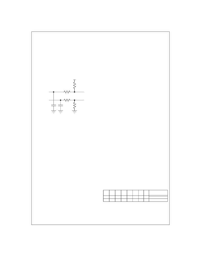
7.1 The USB Pins
Data is received and transmitted through the D+ and D- pins.
These are 3V differential signals. Figure 44 shows the recom-
mended circuitry between the LM9833’s D+ and D- pins and the
scanner’s USB connector.
8.0 Scanning
The following sections describe the typical steps taken to scan an
image.
8.1 Start Scanning - Initiating an Image Scan
An image scan is initiated by writing a Scan command to Register
07. The LM9833 will move the sensor forward the number of full-
steps specified in registers 4A/4B and begin scanning. Scanning
ends when the host writes a new command to the command reg-
ister (Idle, High Speed Forward or High Speed Reverse) or when
PAPER SENSE 1 or PAPER SENSE 2 changes state (if pro-
grammed to do so).
The line buffer is reset when the Scanning bit is SET, not when it
is cleared. The host can continue to read stored data out of the
line buffer after a scan has stopped.
Pixel data is read from configuration register address 00. Regis-
ters at other addresses can be read during a scan (to read the
LM9833’s status registers, abort the scan, etc.).
If for some reason you want to pause the scan for some length of
time and resume later, do NOT stop the scan (return to Idle). Sim-
ply stop reading pixel data. When the buffer fills up, the LM9833
will automatically stop scanning and turn off power to the stepper
motor (when the delay goes beyond the time specified in the Hold
Current Timeout register).
The last 2 bytes of every line is a status word indicating how
much data is in the image buffer at the time the status word was
written. This information is in the 8 LSBs of the status word, and
has the same format as Register 01.
8.2 Reconstructing 8 bit Image Data Received By the PC
When reconstructing an image from the stream of data received
from the LM9833, it is useful to know the format of the data. The
LM9833 does not perform deinterleaving on the pixel data, it
comes out exactly as the sensor sends it. Deinterleaving must be
performed on the host PC.
For a single output CCD/CIS that outputs one line of data with
colors alternating at the line rate, the output format is:
R
1
, R
2
, R
3
, R
4
,..., R
n-2
, R
n-1
, R
n
(line m)
G
1
, G
2
, G
3
, G
4
,..., G
n-2
, G
n-1
, G
n
(line m + 1)
B
1
, B
2
, B
3
, B
4
,..., B
n-2
, B
n-1
, B
n
(line m + 2)
For a triple output CCD/CIS that outputs 3 lines of data (each x
pixels apart in the vertical direction) with colors alternating at the
pixel rate, the output would be:
R
1
, G
1
, B
1
, R
2
, G
2
, B
2
,..., R
n-1
, G
n-1
, B
n-1
, R
n
, G
n
, B
n
with the Red data representing line m+x, the Green data repre-
senting line m, and the Blue data representing line m-x. “x” is the
separation between lines, which depends on the physical dis-
tance between the R, G, and B sensors and the rate at which the
sensor is moving over the image.
The length of a line of image data sent to the PC depends on sev-
eral factors:
The range of pixels to be scanned (Data Pixels): Data Pixels =
(Data Pixels End - Data Pixels Start),
The horizontal resolution set in the configuration register
(HDPI_Divider)
The number of bits per pixel (1, 2, 4, or 8, called B), and
The color mode: pixel rate (C=3) or line rate (C=1).
The scanner software on the host must strip the 2 byte status
word from the end of each line before reconstructing the image.
8.2.1 Reconstructing 16 bit Image Data Received By the PC
In the 16 bit Data Mode the Gamma Correction and Pixel Packing
stages are bypassed. Each pixel comes out as 2 bytes instead of
1, doubling the amount of memory needed to store one line. The
data format is shown in Figure 45. This mode is otherwise identi-
cal to the 8 bit mode. The number of bytes per line in 16 bit mode
is given in this equation:
The 16 bit mode is used to acquire 16 bit data for accurate gain
and offset calibration.
8.3 High Speed Forward
When register 07 is set to a 1, the LM9833 moves the motor for-
ward at maximum speed (determined by the fast feed stepsize,
registers 48 and 49) until a 0 is written to register 07 or either one
Figure 44: Recommended USB Component Values
LM9833 D-
(pin 83)
1.5k
22
LM9833 V
REGULATOR
(pin82)
LM9833 D+
(pin 84)
22
D+ USB
Connector
1M
D- USB
Connector
Optional - forces LM9833 into
suspend mode if USB cable is
not attached to scanner.
10pF 10pF
7
6
5
4
3
2
1
0
Type
b15
b7
b14
b6
b13
b5
b12 b11 b10
b4
b3
b9
b1
b8
b0
First Byte
Second Byte
b2
Figure 45:
16 bit Data Format
Bytes/Line
2
INT
INT
-------------HDPI_16
---Data Pixels
C
B
=
Bytes/Line
2
INT
HDPI_Divider
(
)
C
=
Applications Information
(Continued)
L
相關PDF資料 |
PDF描述 |
|---|---|
| LM98501CCVBH | 10-Bit, 27 MSPS Camera Signal Processor |
| LM98501 | 10-Bit, 27 MSPS Camera Signal Processor |
| LMC555CBPEVAL | CMOS Timer |
| LMC555CN | CMOS Timer |
| LMC555 | CMOS Timer |
相關代理商/技術參數 |
參數描述 |
|---|---|
| LM9833B-F WAF | 制造商:Texas Instruments 功能描述: |
| LM9833CCVJD | 制造商:Texas Instruments 功能描述:USB Image Scanner 100-Pin TQFP |
| LM9833CCVJD NOPB | 制造商:Texas Instruments 功能描述:Bulk |
| LM9833CCVJD/NOPB | 功能描述:視頻模擬/數字化轉換器集成電路 RoHS:否 制造商:Texas Instruments 輸入信號類型:Differential 轉換器數量:1 ADC 輸入端數量:4 轉換速率:3 Gbps 分辨率:8 bit 結構: 輸入電壓:3.3 V 接口類型:SPI 信噪比: 電壓參考: 電源電壓-最大:3.45 V 電源電壓-最小:3.15 V 最大功率耗散: 最大工作溫度:+ 85 C 最小工作溫度:- 40 C 封裝 / 箱體:TCSP-48 封裝:Reel |
| LM98501 | 制造商:NSC 制造商全稱:National Semiconductor 功能描述:10-Bit, 27 MSPS Camera Signal Processor |
發布緊急采購,3分鐘左右您將得到回復。