- 您現在的位置:買賣IC網 > PDF目錄361039 > LMC7225IMX (NATIONAL SEMICONDUCTOR CORP) Micro-Power, Rail-to-Rail CMOS Comparators with Open-Drain/Push-Pull Outputs and TinyPak⑩ Package PDF資料下載
參數資料
| 型號: | LMC7225IMX |
| 廠商: | NATIONAL SEMICONDUCTOR CORP |
| 元件分類: | 運動控制電子 |
| 英文描述: | Micro-Power, Rail-to-Rail CMOS Comparators with Open-Drain/Push-Pull Outputs and TinyPak⑩ Package |
| 中文描述: | COMPARATOR, 6000 uV OFFSET-MAX, 24000 ns RESPONSE TIME, PDSO8 |
| 封裝: | SOIC-8 |
| 文件頁數: | 4/11頁 |
| 文件大小: | 360K |
| 代理商: | LMC7225IMX |
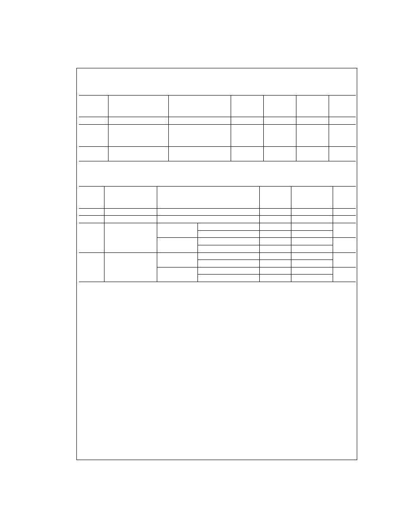
2.7V to 5V Electrical Characteristics
(Continued)
Unless otherwise specified, all limits guaranteed for T
J
= 25C, V
+
= 2.7V to 5V, V
= 0V, V
CM
= V
O
= V+/2.
Boldface
limits
apply at the temperature extremes.
Typ
LMC7215
Limit
(Note 6)
LMC7225
Limit
(Note 6)
Symbol
Parameter
Conditions
(Note 5)
Units
Current (Note 10)
Output Leakage Current
V
+
= 5.0V, Sinking
V
+
= 2.2V
V
IN
+ = 0.1V, V
IN
= 0V,
V
OUT
= 15V
V
+
= 5.0V
V
IN
+ = 5V, V
IN
= 0V
30
mA
nA
max
I
Leakage
0.01
NA
500
I
S
Supply Current
0.7
1
1
μA
max
1.2
1.2
AC Electrical Characteristics
Unless otherwise specified, T
J
= 25C, V
+
= 5V, V
= 0V, V
CM
= V
+
/2
LMC7215
Typ
(Note 5)
1
0.4
24
12
17
11
24
12
17
11
LMC7225
Typ
(Notes 5, 8)
12.2
0.35
24
12
17
11
29
17
22
16
Symbol
Parameter
Conditions
Units
t
rise
t
fall
t
PHL
Rise Time
Fall Time
Propagation Delay
(High to Low)
Overdrive = 10 mV (Note 8)
Overdrive = 10 mV (Note 8)
(Notes 8, 9)
μs
μs
μs
Overdrive = 10 mV
Overdrive = 100 mV
Overdrive = 10 mV
Overdrive = 100 mV
Overdrive = 10 mV
Overdrive = 100 mV
Overdrive = 10 mV
Overdrive = 100 mV
V
+
= 2.7V
(Notes 8, 9)
(Notes 8, 9)
μs
t
PLH
Propagation Delay
(Low to High)
μs
V
+
= 2.7V
(Notes 8, 9)
μs
Note 1:
Absolute Maximum Ratings indicate limits beyond which damage to the device may occur. Operating Ratings indicate conditions for which the device is in-
tended to be functional, but specific performance is not guaranteed. For guaranteed specifications and the test conditions, see the Electrical Characteristics.
Note 2:
Human body model, 1.5 k
in series with 100 pF.
Note 3:
Applies to both single-supply and split-supply operation. Continuous short circuit operation at elevated ambient temperature can result in exceeding the
maximum allowed junction temperature of 150C.
Note 4:
The maximum power dissipation is a function of T
J(max)
,
θ
JA
, and T
A
. The maximum allowable power dissipation at any ambient temperature is
P
D
= (T
J(max)
T
A
)/
θ
JA
. All numbers apply for packages soldered directly into a PC board.
Note 5:
Typical values represent the most likely parametric norm.
Note 6:
All limits are guaranteed by testing or statistical analysis.
Note 7:
CMRR measured at V
= 0V to 2.5V and 2.5V to 5V when V
= 5V, V
CM
= 0.2V to 1.35V and 1.35V to 2.7V when V
S
= 2.7V. This eliminates units that
have large V
OS
at the V
CM
extremes and low or opposite V
OS
at V
CM
= V
S
/2.
Note 8:
All measurements made at 10 kHz.A100 k
pull-up resistor was used when measuring the LMC7225. C
LOAD
=50 pF including the test jig and scope probe.
The rise times of the LMC7225 are a function of the R-C time constant.
Note 9:
Input step voltage for the propagation measurements is 100 mV.
Note 10:
Do not short the output of the LMC7225 to voltages greater than 10V or damage may occur.
www.national.com
4
相關PDF資料 |
PDF描述 |
|---|---|
| LMC7221BIM | Tiny CMOS Comparator with Rail-To-Rail Input and Open Drain Output |
| LMC7221BIM5 | Tiny CMOS Comparator with Rail-To-Rail Input and Open Drain Output |
| LMC7221AIN | IC-CMOS COMPARATOR |
| LMC7221BIM5X | Tiny CMOS Comparator with Rail-To-Rail Input and Open Drain Output |
| LMC7221BIMX | Tiny CMOS Comparator with Rail-To-Rail Input and Open Drain Output |
相關代理商/技術參數 |
參數描述 |
|---|---|
| LMC7345A WAF | 制造商:Texas Instruments 功能描述: |
| LMC7532 | 制造商:未知廠家 制造商全稱:未知廠家 功能描述: |
| LMC7660 | 制造商:NSC 制造商全稱:National Semiconductor 功能描述:Switched Capacitor Voltage Converter |
| LMC7660IM | 功能描述:電荷泵 RoHS:否 制造商:Maxim Integrated 功能:Inverting, Step Up 輸出電壓:- 1.5 V to - 5.5 V, 3 V to 11 V 輸出電流:100 mA 電源電流:1 mA 最大工作溫度:+ 70 C 封裝 / 箱體:SOIC-8 Narrow 封裝:Tube |
| LMC7660IM/NOPB | 功能描述:電荷泵 Switched Cap Vltg Converter RoHS:否 制造商:Maxim Integrated 功能:Inverting, Step Up 輸出電壓:- 1.5 V to - 5.5 V, 3 V to 11 V 輸出電流:100 mA 電源電流:1 mA 最大工作溫度:+ 70 C 封裝 / 箱體:SOIC-8 Narrow 封裝:Tube |
發布緊急采購,3分鐘左右您將得到回復。