- 您現在的位置:買賣IC網 > PDF目錄361040 > LMH6738 (National Semiconductor Corporation) Very Wideband, Low Distortion Triple Op Amp PDF資料下載
參數資料
| 型號: | LMH6738 |
| 廠商: | National Semiconductor Corporation |
| 英文描述: | Very Wideband, Low Distortion Triple Op Amp |
| 中文描述: | 非常寬帶,低失真三運算放大器 |
| 文件頁數: | 8/12頁 |
| 文件大小: | 432K |
| 代理商: | LMH6738 |
Application Section
GENERAL INFORMATION
The LMH6738 is a high speed current feedback amplifier,
optimized for very high speed and low distortion. The
LMH6738 has no internal ground reference so single or split
supply configurations are both equally useful.
EVALUATION BOARDS
National Semiconductor provides the following evaluation
boards as a guide for high frequency layout and as an aid in
device testing and characterization. Many of the datasheet
plots were measured with these boards.
Device
Package
Evaluation Board
Part Number
LMH730275
LMH6738MQA
SSOP
Abare evaluation board is shipped when a sample request is
placed with National Semiconductor.
FEEDBACK RESISTOR SELECTION
One of the key benefits of a current feedback operational
amplifier is the ability to maintain optimum frequency re-
sponse independent of gain by using appropriate values for
the feedback resistor (R
F
). The Electrical Characteristics and
Typical Performance plots specify an R
F
of 550
, a gain of
+2 V/V and
±
5V power supplies (unless otherwise speci-
fied). Generally, lowering R
F
from it’s recommended value
will peak the frequency response and extend the bandwidth
while increasing the value of R
F
will cause the frequency
response to roll off faster. Reducing the value of R
F
too far
below it’s recommended value will cause overshoot, ringing
and, eventually, oscillation.
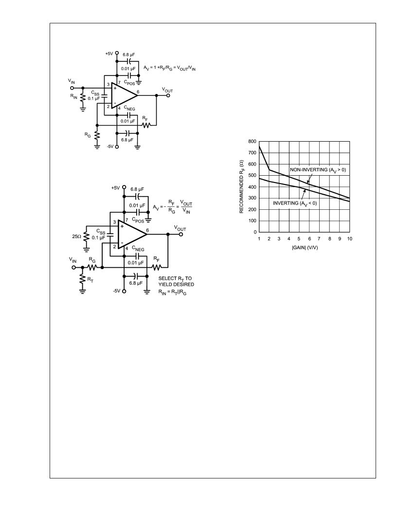
See
Figure 3
, Recommended R
. vs Gain for selecting a
feedback resistor value for gains of
±
1 to
±
10. Since each
application is slightly different it is worth some experimenta-
tion to find the optimal R
for a given circuit. In general a
value of R
that produces~.1 dB of peaking is the best
compromise between stability and maximal bandwidth. Note
that it is not possible to use a current feedback amplifier with
the output shorted directly to the inverting input. The buffer
configuration of the LMH6738 requires a 750
feedback
resistor for stable operation.
The LMH6738 was optimized for high speed operation. As
shown in
Figure 3
the suggested value for R
F
decreases for
higher gains. Due to the impedance of the input buffer there
is a practical limit for how small R
can go, based on the
lowest practical value of R
. This limitation applies to both
inverting and non inverting configurations. For the LMH6738
the input resistance of the inverting input is approximately
30
and 20
is a practical (but not hard and fast) lower limit
for R
. The LMH6738 begins to operate in a gain bandwidth
limited fashion in the region where R
is nearly equal to the
input buffer impedance. Note that the amplifier will operate
with R
values well below 20
, however results may be
substantially different than predicted from ideal models. In
particular the voltage potential between the Inverting and
Non Inverting inputs cannot be expected to remain small.
Inverting gain applications that require impedance matched
inputs may limit gain flexibility somewhat (especially if maxi-
mum bandwidth is required). The impedance seen by the
source is R
G
|| R
T
(R
T
is optional). The value of R
G
is R
F
20097505
FIGURE 1. Recommended Non-Inverting Gain Circuit
20097506
FIGURE 2. Recommended Inverting Gain Circuit
20097503
FIGURE 3. Recommended R
F
vs. Gain
L
www.national.com
8
相關PDF資料 |
PDF描述 |
|---|---|
| LMH6738MQ | Very Wideband, Low Distortion Triple Op Amp |
| LMP2011 | High Precision, Rail-to-Rail Output Operational Amplifier |
| LMP2011MA | TOOL HAND CRIMP 18-22AWG |
| LMP2011MAX | High Precision, Rail-to-Rail Output Operational Amplifier |
| LMP2011MF | High Precision, Rail-to-Rail Output Operational Amplifier |
相關代理商/技術參數 |
參數描述 |
|---|---|
| LMH6738MQ | 功能描述:運算放大器 - 運放 RoHS:否 制造商:STMicroelectronics 通道數量:4 共模抑制比(最小值):63 dB 輸入補償電壓:1 mV 輸入偏流(最大值):10 pA 工作電源電壓:2.7 V to 5.5 V 安裝風格:SMD/SMT 封裝 / 箱體:QFN-16 轉換速度:0.89 V/us 關閉:No 輸出電流:55 mA 最大工作溫度:+ 125 C 封裝:Reel |
| LMH6738MQ/NOPB | 功能描述:運算放大器 - 運放 Triple Video Op-Amp RoHS:否 制造商:STMicroelectronics 通道數量:4 共模抑制比(最小值):63 dB 輸入補償電壓:1 mV 輸入偏流(最大值):10 pA 工作電源電壓:2.7 V to 5.5 V 安裝風格:SMD/SMT 封裝 / 箱體:QFN-16 轉換速度:0.89 V/us 關閉:No 輸出電流:55 mA 最大工作溫度:+ 125 C 封裝:Reel |
| LMH6738MQX | 功能描述:運算放大器 - 運放 RoHS:否 制造商:STMicroelectronics 通道數量:4 共模抑制比(最小值):63 dB 輸入補償電壓:1 mV 輸入偏流(最大值):10 pA 工作電源電壓:2.7 V to 5.5 V 安裝風格:SMD/SMT 封裝 / 箱體:QFN-16 轉換速度:0.89 V/us 關閉:No 輸出電流:55 mA 最大工作溫度:+ 125 C 封裝:Reel |
| LMH6738MQX/NOPB | 功能描述:運算放大器 - 運放 RoHS:否 制造商:STMicroelectronics 通道數量:4 共模抑制比(最小值):63 dB 輸入補償電壓:1 mV 輸入偏流(最大值):10 pA 工作電源電壓:2.7 V to 5.5 V 安裝風格:SMD/SMT 封裝 / 箱體:QFN-16 轉換速度:0.89 V/us 關閉:No 輸出電流:55 mA 最大工作溫度:+ 125 C 封裝:Reel |
| LMH6739 | 制造商:NSC 制造商全稱:National Semiconductor 功能描述:Very Wideband, Low Distortion Triple Video Buffer |
發布緊急采購,3分鐘左右您將得到回復。