- 您現在的位置:買賣IC網 > PDF目錄369810 > LOC210P NPN-OUTPUT DC-INPUT OPTOCOUPLER PDF資料下載
參數資料
| 型號: | LOC210P |
| 英文描述: | NPN-OUTPUT DC-INPUT OPTOCOUPLER |
| 中文描述: | npn型輸出DC -輸入光耦合器 |
| 文件頁數: | 1/5頁 |
| 文件大小: | 131K |
| 代理商: | LOC210P |
Part #
LOC210P
LOC210PTR
Description
16 Pin Flatpack (50/Tube)
16 Pin Flatpack (1000/Reel)
www.clare.com
DS-LOC210-R4.0
LOC210
Linear Optocouplers
1
Applications
Modem Transformer Replacement With No
Insertion Loss
Digital Telephone Isolation
Power Supply Feedback Voltage/Current
Medical Sensor Isolation
Audio Signal Interfacing
Isolation of Process Control Transducers
Features
16 Pin SOIC Package (PCMCIA Compatible)
Couples Analog and Digital Signals
Wide Bandwidth (>200kHz)
High Gain Stability
Low Input/Output Capacitance
Low Power Consumption
0.01% Servo Linearity
THD 87dB Typical
Machine Insertable, Wave Solderable
Surface Mount and Tape Reel Versions Available
VDE Compatible
Description
The LOC210 Dual Linear Optocoupler features an
infrared LED optically coupled with two phototransis-
tors. One feedback (input) phototransistor is used to
generate a control signal that provides a servomech-
anism to the LED drive current, thus compensating
for the LEDs nonlinear time and temperature charac-
teristics. The other (output) phototransistor provides
an output signal that is linear with respect to the
servo LED current. The product features wide band-
width, high input to output isolation and excellent
servo linearity.
Approvals
UL Recognized: File Number E76270
CSA Certified: File Number LR 43639-10
BSI Certified:
BS EN 60950:1992 (BS7002:1992)
Certificate #:7344
BS EN 41003:1993
Certificate #:7344
Ordering Information
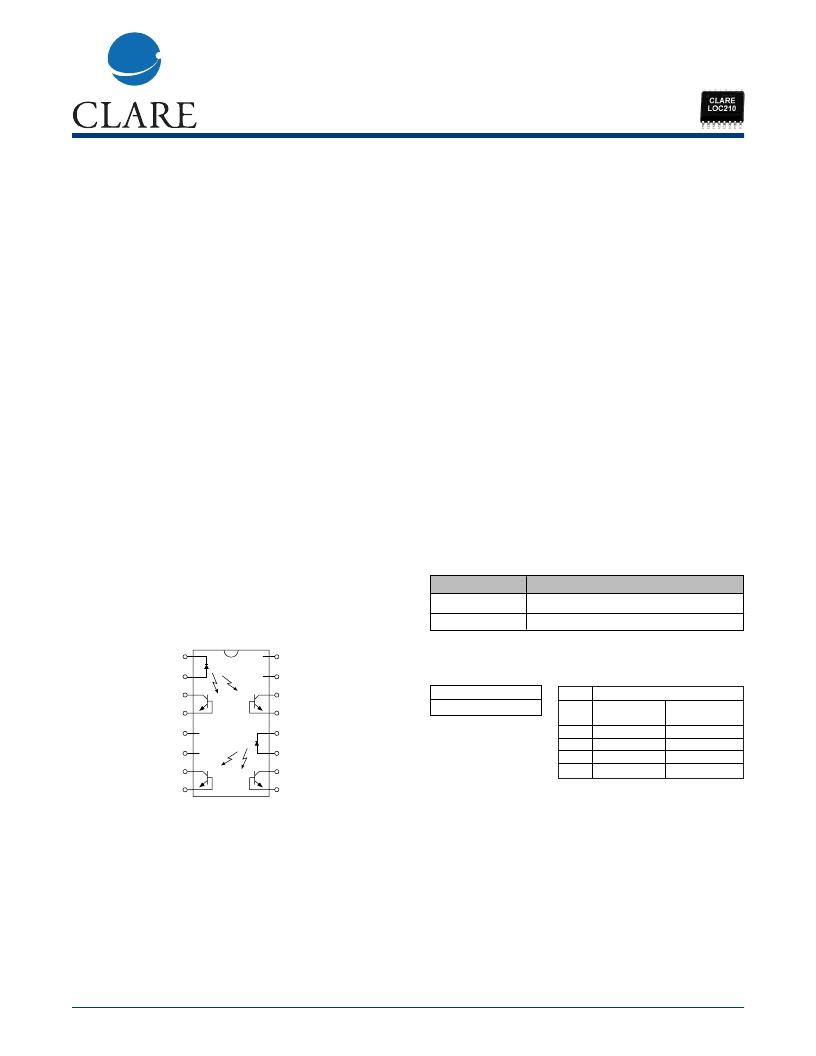
Pin Configuration
LOC210 Pinout
– LED
+ LED
+ V
cc
I
1
NC
NC
+V
cc
I
2
+V
cc
I
1
NC
NC
+V
cc
I
2
1
2
3
4
16
15
14
13
5
6
7
8
12
11
10
9
– LED
+ LED
K3 Sorted Bins
Bin 1 = 0.773 - 0.886
Bin 2 = 0.887 - 1.072
Bin Matrix
Suffix
Bin
Top Pole
Optocoupler*
1
1
2
2
Bottom Pole
Optocoupler**
1
2
1
2
K
L
M
N
*Top Pole Optocoupler: Pins 1,2,3,4,13, and 14
**Bottom Pole Optocouplers: Pins 7 through 12
Part Number Information
The LOC210 are shipped in anti-static tubes (50
pieces each) or tape/reel (1,000 pieces each). Each
container has only 1 bin combination which will be
branded on each part with the appropriate bin letter
K, L, M, or N in the lower right hand corner. Suffix
representation is described in the “Bin Matrix”.
相關PDF資料 |
PDF描述 |
|---|---|
| LOC210PG | NPN-OUTPUT DC-INPUT OPTOCOUPLER |
| LOW-COST | Low-Cost PWM Controller (110k) |
| LOW | Low Capacitance Devices (39k) |
| LP0801K1 | TRANSISTOR | MOSFET | P-CHANNEL | 16.5V V(BR)DSS | TO-236AB |
| LP183 | Filter & Ring Core Chokes |
相關代理商/技術參數 |
參數描述 |
|---|---|
| LOC210PG | 制造商:未知廠家 制造商全稱:未知廠家 功能描述:NPN-OUTPUT DC-INPUT OPTOCOUPLER |
| LOC210PTR | 功能描述:高線性光耦合器 Dual Linear Optocoupler RoHS:否 制造商:Avago Technologies 輸入類型:AC/DC 最大正向二極管電壓:1.95 V 最大反向二極管電壓:2.5 V 最大輸入二極管電流:25 mA 最大功率耗散:60 mW 最大工作溫度:+ 100 C 最小工作溫度:- 55 C 封裝 / 箱體:DIP-8 Gull Wing 封裝:Tube |
| LOC211 | 制造商:CLARE 制造商全稱:Clare, Inc. 功能描述:Linear Optocouplers |
| LOC211P | 功能描述:高線性光耦合器 Dual Linear Optocoupler RoHS:否 制造商:Avago Technologies 輸入類型:AC/DC 最大正向二極管電壓:1.95 V 最大反向二極管電壓:2.5 V 最大輸入二極管電流:25 mA 最大功率耗散:60 mW 最大工作溫度:+ 100 C 最小工作溫度:- 55 C 封裝 / 箱體:DIP-8 Gull Wing 封裝:Tube |
| LOC211P-N | 制造商:IXYS Integrated Circuits Division 功能描述:LOC211P-N |
發布緊急采購,3分鐘左右您將得到回復。