- 您現(xiàn)在的位置:買賣IC網(wǎng) > Datasheet目錄55 > MAX2850ITK+ (Maxim Integrated)TRANSMITTER MIMO 5GHZ 4CH 68TQFN Datasheet資料下載
參數(shù)資料
| 型號(hào): | MAX2850ITK+ |
| 廠商: | Maxim Integrated |
| 文件頁(yè)數(shù): | 5/33頁(yè) |
| 文件大小: | 4689K |
| 描述: | TRANSMITTER MIMO 5GHZ 4CH 68TQFN |
| 產(chǎn)品培訓(xùn)模塊: | Lead (SnPb) Finish for COTS Obsolescence Mitigation Program |
| 標(biāo)準(zhǔn)包裝: | 30 |
| 頻率: | 4.9GHz ~ 5.9GHz |
| 應(yīng)用: | 通用 |
| 功率 - 輸出: | -4dBm |
| 電流 - 傳輸: | 661mA |
| 數(shù)據(jù)接口: | PCB,表面貼裝 |
| 天線連接器: | PCB,表面貼裝 |
| 電源電壓: | 2.7 V ~ 3.6 V |
| 封裝/外殼: | 68-TQFN 裸露焊盤 |
| 包裝: | 管件 |
第1頁(yè)第2頁(yè)第3頁(yè)第4頁(yè)當(dāng)前第5頁(yè)第6頁(yè)第7頁(yè)第8頁(yè)第9頁(yè)第10頁(yè)第11頁(yè)第12頁(yè)第13頁(yè)第14頁(yè)第15頁(yè)第16頁(yè)第17頁(yè)第18頁(yè)第19頁(yè)第20頁(yè)第21頁(yè)第22頁(yè)第23頁(yè)第24頁(yè)第25頁(yè)第26頁(yè)第27頁(yè)第28頁(yè)第29頁(yè)第30頁(yè)第31頁(yè)第32頁(yè)第33頁(yè)
5GHz, 4-Channel MIMO Transmitter
_______________________________________________________________________________________ 5
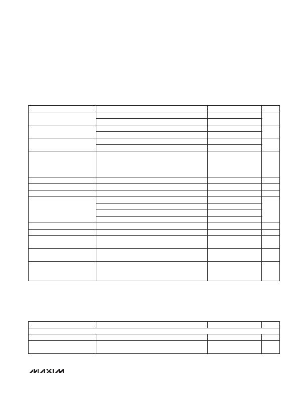
AC ELECTRICAL CHARACTERISTICSRx MODE (continued)
(Operating conditions, unless otherwise specified: V
CC
= 2.7V~3.6V, RF frequency = 5.351GHz, T
A
= -25NC to +85NC. LO frequency
= 5.35GHz. Reference frequency = 40MHz, ENABLE = high, CS = high, SCLK = DIN = low, with power matching at RXRF+ and
RXRF- differential ports using the Typical Operating Circuit. Receiver I/Q output at 100mV
RMS
loaded with 10kI differential load
resistance and 10pF load capacitance. The RSSI pin is loaded with 10kI load resistance to ground. Typical values measured at V
CC
= 2.85V, channel bandwidths of 40MHz, T
A
= +25NC.) (Note 1)
AC ELECTRICAL CHARACTERISTICSTx MODE
(Operating conditions, unless otherwise specified: V
CC
= 2.7V~3.6V, RF frequency = 5.351GHz, T
A
= -25NC to +85NC. LO frequency
= 5.35GHz. Reference frequency = 40MHz, ENABLE = high, CS = high, SCLK = DIN = low, with power matching at TXRF+ and
TXRF- differential ports using the Typical Operating Circuit. 100mV
RMS
sine and cosine signal applied to I/Q baseband inputs of
transmitter (differential DC-coupled). Typical values measured at V
CC
= 2.85V, channel bandwidths of 40MHz, T
A
= +25NC.) (Note 1)
PARAMETER
CONDITIONS
MIN
TYP
MAX
UNITS
Baseband -3dB Lowpass Corner
Frequency
Main address 0 D1 = 0
9.5
MHz
Main address 0 D1 = 1
19
Baseband Filter Stopband
Rejection
Rejection at 30MHz offset frequency for 20MHz channel
57
70
dB
Rejection at 60MHz offset frequency for 40MHz channel
57
70
Baseband -3dB Highpass Corner
Frequency
Main address 5 D1 = 1
600
kHz
Main address 5 D1 = 0
10
Steady-State I/Q Output DC Error
with AC-Coupling
50Fs after enabling receive mode and toggling RxHP
from 1 to 0, averaged over many measurements if I/Q
noise voltage exceeds 1mV
RMS
, at any given gain set-
ting, no input signal, 1-sigma value
2
mV
I/Q Gain Imbalance
1MHz baseband output, 1-sigma value
0.1
dB
I/Q Phase Imbalance
1MHz baseband output, 1-sigma value
0.2
degrees
Sideband Suppression
1MHz baseband output (Note 2)
40
dB
Receiver Spurious Signal
Emissions
LO frequency
-75
dBm/
MHz
2 x LO frequency
-62
3 x LO frequency
-75
4 x LO frequency
-60
RF RSSI Output Voltage
-20dBm input power
1.75
V
Baseband RSSI Slope
19.5
26.5
35.5
mV/dB
Baseband RSSI Maximum Output
Voltage
2.3
V
Baseband RSSI Minimum Output
Voltage
0.5
V
RF Loopback Conversion Gain
Tx VGA gain at maximum (Main address 9 D9:D4
= 111111); Rx VGA gain at maximum - 24dB (Main
address 1 D3:D0 = 0101)
-6
+2
+10
dB
PARAMETER
CONDITIONS
MIN
TYP
MAX
UNITS
TRANSMIT SECTION: Tx BASEBAND I/Q INPUTS TO RF OUTPUTS (Includes Matching and Balun Loss)
RF Output Frequency Range
4.9
5.9
GHz
Peak-to-Peak Gain Variation over
RF Band
At one temperature
3
6.4
dB
相關(guān)PDF資料 |
PDF描述 |
|---|---|
| MAX7057ASE+T | IC TRANSMITTER ASK/FSK 16-SOIC |
| MBA-2060 | ANTENNA METROLOGY BICONICAL |
| MC33493ADTBER2 | IC RF TRANSMITTER UHF 14-TSSOP |
| MDEV-916-ES | KIT MASTER DEVELOP 916MHZ ES SRS |
| MICRF102YM TR | IC TRANSMITTER ASK UHF 8-SOIC |
相關(guān)代理商/技術(shù)參數(shù) |
參數(shù)描述 |
|---|---|
| MAX2850ITK+ | 功能描述:射頻發(fā)射器 5GHZ 4Ch MIMO Transmitter RoHS:否 制造商:Micrel 類型:ASK Transmitter 封裝 / 箱體:SOT-23-6 工作頻率:300 MHz to 450 MHz 封裝:Reel |
| MAX2850ITK+T | 功能描述:射頻發(fā)射器 5GHZ 4Ch MIMO Transmitter RoHS:否 制造商:Micrel 類型:ASK Transmitter 封裝 / 箱體:SOT-23-6 工作頻率:300 MHz to 450 MHz 封裝:Reel |
| MAX2851ITK+ | 功能描述:射頻接收器 RF and RFID 射頻接收器s - TRANSMITTER MIMO 5GHZ 5CH 68TQFN RoHS:否 制造商:Skyworks Solutions, Inc. 類型:GPS Receiver 封裝 / 箱體:QFN-24 工作頻率:4.092 MHz 工作電源電壓:3.3 V 封裝:Reel |
| MAX2851ITK+T | 功能描述:射頻接收器 RF and RFID 射頻接收器s - TRANSMITTER MIMO 5GHZ 5CH 68TQFN RoHS:否 制造商:Skyworks Solutions, Inc. 類型:GPS Receiver 封裝 / 箱體:QFN-24 工作頻率:4.092 MHz 工作電源電壓:3.3 V 封裝:Reel |
| MAX2852ITK+ | 功能描述:射頻接收器 5Ghz Receiver RoHS:否 制造商:Skyworks Solutions, Inc. 類型:GPS Receiver 封裝 / 箱體:QFN-24 工作頻率:4.092 MHz 工作電源電壓:3.3 V 封裝:Reel |
發(fā)布緊急采購(gòu),3分鐘左右您將得到回復(fù)。