- 您現(xiàn)在的位置:買賣IC網(wǎng) > Datasheet目錄43 > MAX5926EEE+ (Maxim Integrated)IC HOT-SWAP CONTROLLER 16QSOP-EP Datasheet資料下載
參數(shù)資料
| 型號(hào): | MAX5926EEE+ |
| 廠商: | Maxim Integrated |
| 文件頁(yè)數(shù): | 17/21頁(yè) |
| 文件大小: | 333K |
| 描述: | IC HOT-SWAP CONTROLLER 16QSOP-EP |
| 產(chǎn)品培訓(xùn)模塊: | Lead (SnPb) Finish for COTS Obsolescence Mitigation Program |
| 標(biāo)準(zhǔn)包裝: | 100 |
| 類型: | 熱交換控制器 |
| 應(yīng)用: | 通用 |
| 內(nèi)部開關(guān): | 無(wú) |
| 電源電壓: | 1 V ~ 13.2 V |
| 工作溫度: | -40°C ~ 85°C |
| 安裝類型: | 表面貼裝 |
| 封裝/外殼: | 16-LSSOP(0.154",3.90mm 寬) |
| 供應(yīng)商設(shè)備封裝: | 16-QSOP 裸露焊盤 |
| 包裝: | 管件 |
第1頁(yè)第2頁(yè)第3頁(yè)第4頁(yè)第5頁(yè)第6頁(yè)第7頁(yè)第8頁(yè)第9頁(yè)第10頁(yè)第11頁(yè)第12頁(yè)第13頁(yè)第14頁(yè)第15頁(yè)第16頁(yè)當(dāng)前第17頁(yè)第18頁(yè)第19頁(yè)第20頁(yè)第21頁(yè)
1V to 13.2V, n-Channel Hot-Swap Controllers
Require No Sense Resistor
______________________________________________________________________________________ 17
Circuit-Breaker Temperature Coefficient
In applications where the external MOSFETs on-resis-
tance is used as a sense resistor to determine overcur-
rent conditions, a 3300ppm/癈 temperature coefficient
is desirable to compensate for the R
DS(ON)
tempera-
ture coefficient. Use the MAX5926s TC input to select
the circuit-breaker programming currents temperature
coefficient, TC
ICB
(see Table 2). The MAX5924 temper-
ature coefficient is preset to 0ppm/癈, and the
MAX5925s is preset to 3300ppm/癈.
Setting TC
ICB
to 3300ppm/癈 allows the circuit-breaker
threshold to track and compensate for the increase in the
MOSFETs R
DS(ON)
with increasing temperature. Most
MOSFETs have a temperature coefficient within a
3000ppm/癈 to 7000ppm/癈 range. Refer to the MOSFET
data sheet for a device-specific temperature coefficent.
R
DS(ON)
and I
CB
are temperature dependent, and can
therefore be expressed as functions of temperature. At
a given temperature, the MAX5925/MAX5926 indicate
an overcurrent condition when:
I
TRIPSLOW
x R
DS(ON)
(T) e I
CB
(T) x R
CB
+ |V
CB,OS
|
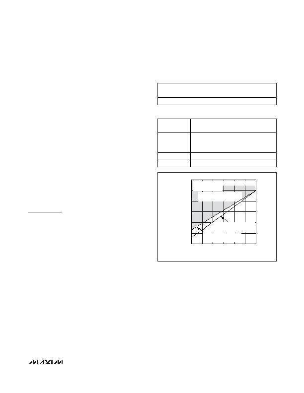
where V
CB,OS
is the worst-case offset voltage. Figure 14
graphically portrays operating conditions for a MOSFET
with a 4500ppm/癈 temperature coefficient.
Applications Information
Component Selection
n-Channel MOSFET
Most circuit component values may be calculated with
the aid of the MAX5924MAX5926. The "Design calcula-
tor for choosing component values" software can be
downloaded from the MAX5924MAX5926 Quickview on
the Maxim website.
Select the external n-channel MOSFET according to the
applications current and voltage level. Table 3 lists some
recommended components. Choose the MOSFETs
on-resistance, R
DS(ON)
, low enough to have a minimum
voltage drop at full load to limit the MOSFET power dis-
sipation. High R
DS(ON)
can cause undesired power
loss and output ripple if the board has pulsing loads or
triggers an external undervoltage reset monitor at full
load. Determine the device power-rating requirement to
accommodate a short circuit on the board at startup
with the device configured in autoretry mode.
Using the MAX5924/MAX5925/MAX5926 in latched mode
allows the consideration of MOSFETs with higher R
DS(ON)
and lower power ratings. A MOSFET can typically with-
stand single-shot pulses with higher dissipation than the
specified package rating. Low MOSFET gate capaci-
tance is not necessary since the inrush current limiting is
achieved by limiting the gate dv/dt. Table 4 lists some
recommended manufacturers and components.
Be sure to select a MOSFET with an appropriate gate
drive (see the Typical Operating Characteristics).
Typically, for V
CC
less than 3V, select a 2.5V V
GS
MOSFET.
Table 2. Programming the Temperature
Coefficient (MAX5926)
TC
TC
ICB
(ppm/癈)
High
0
Low
3300
Table 3. Suggested External MOSFETs
APPLICATION
CURRENT (A)
PART
DESCRIPTION
1
International Rectifier
IRF7401
SO-8
2
Siliconix Si4378DY
SO-8
5
Siliconix SUD40N02-06
DPAK
10
Siliconix SUB85N02-03
D2PAK
TEMPERATURE (癈)
85
60
35
10
-15
25
30
35
40
45
50
20
-40
110
V
S
= V
CC
= 13.2V, R
CB
= 672&, I
TRIPSLOW
= 5A,
R
DS(ON)
(25) = 6.5m&
CIRCUIT-BREAKER TRIP REGION
(V
SENSE
e V
CB
)
V
CB
= I
CB
(T) x R
CB
+ V
CB,OS
(3300ppm/癈)
V
SENSE
= R
DS(ON)
(T) x I
LOAD(MAX)
(4500ppm/癈)
Figure 14. Circuit-Breaker Trip Point and Current-Sense
Voltage vs. Temperature
相關(guān)PDF資料 |
PDF描述 |
|---|---|
| MAX5929BEEG+ | IC HOT SWAP CTLR QUAD 24QSOP |
| MAX5930AEEG+ | IC HOT SWAP CTLR PWR SEQ 24QSOP |
| MAX5932ESA+T | IC HOT-SWAP CONTROLLER 8-SOIC |
| MAX5933EESA+ | IC HOT-SWAP CONTROLLER 8-SOIC |
| MAX5934EEE+ | IC HOT-SWAP CONTROLLER 16-QSOP |
相關(guān)代理商/技術(shù)參數(shù) |
參數(shù)描述 |
|---|---|
| MAX5926EEE+ | 功能描述:熱插拔功率分布 1-13.2V Hot-Swap Controller RoHS:否 制造商:Texas Instruments 產(chǎn)品:Controllers & Switches 電流限制: 電源電壓-最大:7 V 電源電壓-最小:- 0.3 V 工作溫度范圍: 功率耗散: 安裝風(fēng)格:SMD/SMT 封裝 / 箱體:MSOP-8 封裝:Tube |
| MAX5926EEE+T | 功能描述:熱插拔功率分布 1-13.2V Hot-Swap Controller RoHS:否 制造商:Texas Instruments 產(chǎn)品:Controllers & Switches 電流限制: 電源電壓-最大:7 V 電源電壓-最小:- 0.3 V 工作溫度范圍: 功率耗散: 安裝風(fēng)格:SMD/SMT 封裝 / 箱體:MSOP-8 封裝:Tube |
| MAX5926EEE-T | 功能描述:熱插拔功率分布 RoHS:否 制造商:Texas Instruments 產(chǎn)品:Controllers & Switches 電流限制: 電源電壓-最大:7 V 電源電壓-最小:- 0.3 V 工作溫度范圍: 功率耗散: 安裝風(fēng)格:SMD/SMT 封裝 / 箱體:MSOP-8 封裝:Tube |
| MAX5926EVKIT | 制造商:Maxim Integrated Products 功能描述:1V TO 13.2V N-CHANNEL HOT-SWAP CON - Rail/Tube |
| MAX5927AETJ+ | 功能描述:熱插拔功率分布 Quad Hot-Swap Controller RoHS:否 制造商:Texas Instruments 產(chǎn)品:Controllers & Switches 電流限制: 電源電壓-最大:7 V 電源電壓-最小:- 0.3 V 工作溫度范圍: 功率耗散: 安裝風(fēng)格:SMD/SMT 封裝 / 箱體:MSOP-8 封裝:Tube |
發(fā)布緊急采購(gòu),3分鐘左右您將得到回復(fù)。