- 您現在的位置:買賣IC網 > Datasheet目錄43 > MAX5986AETE+ (Maxim Integrated)IC POE SWITCH PSE 16TQFN Datasheet資料下載
參數資料
| 型號: | MAX5986AETE+ |
| 廠商: | Maxim Integrated |
| 文件頁數: | 2/23頁 |
| 文件大小: | 843K |
| 描述: | IC POE SWITCH PSE 16TQFN |
| 標準包裝: | 60 |
| 類型: | 以太網供電控制器 PD 開關(PoE) |
| 應用: | 供電設備(PSE) |
| 內部開關: | 是 |
| 電流限制: | 201mA |
| 電源電壓: | 8.7 V ~ 60 V |
| 工作溫度: | -40°C ~ 85°C |
| 安裝類型: | 表面貼裝 |
| 封裝/外殼: | 16-WQFN 裸露焊盤 |
| 供應商設備封裝: | 16-TQFN-EP(5x5) |
| 包裝: | 管件 |
MAX5986AMAX5986C/MAX5987A
IEEE 802.3af-Compliant, High-Efficiency, Class 1/
Class 2, PDs with Integrated DC-DC Converter
2
Maxim Integrated
Junction-to-Ambient Thermal Resistance (q
JA
) ..............35癈/W
Junction-to-Case Thermal Resistance (q
JC
) ..................2.7癈/W
ABSOLUTE MAXIMUM RATINGS
Stresses beyond those listed under
Absolute Maximum Ratings
may cause permanent damage to the device. These are stress ratings only, and functional opera-
tion of the device at these or any other conditions beyond those indicated in the operational sections of the specifications is not implied. Exposure to absolute
maximum rating conditions for extended periods may affect device reliability.
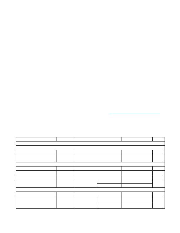
PACKAGE THERMAL CHARACTERISTICS (Note 2)
Note 2: Package thermal resistances were obtained using the method described in JEDEC specification JESD51-7, using a four-layer
board. For detailed information on package thermal considerations, refer to www.maximintegrated.com/thermal-tutorial.
(All voltages referenced to GND, unless otherwise noted.)
V
DD
to GND ...........................................................-0.3V to +70V
(100V, 100ms, R
TEST
= 3.3k? (Note 1)
V
CC
, WAD, RREF to GND ........................ -0.3V to (V
DD
+ 0.3V)
AUX, LDO_IN, LED to GND .................................... -0.3V to 16V
LDO_OUT to GND .............................. -0.3V to (LDO_IN + 0.3V)
LDO_FB to GND ......................................................-0.3V to +6V
LX to GND ................................................ -0.3V to (V
CC
+ 0.3V)
LDO_OUT, VDRV, FB, RESET, WK, SL, ULP, MPS, CLASS2
to GND ..............................................................-0.3V to +6V
VDRV to V
DD
............................................ -0.3V to (V
DD
+ 0.3V)
PGND to GND ......................................................-0.3V to +0.3V
LX Total RMS Current ...........................................................1.6A
Continuous Power Dissipation (T
A
= + 70NC)
TQFN (derate 28.6mW/NC above +70NC) ..............2285.7mW
Operating Temperature Range ..........................-40NC to +85NC
Junction Temperature .....................................................+150NC
Storage Temperature Range ............................-65NC to +150NC
Lead Temperature (soldering, 10s) ................................+300NC
Soldering Temperature (reflow) ......................................+260NC
Note 1: See Figure 1, Test Circuit.
ELECTRICAL CHARACTERISTICS
(V
DD
= 48V, R
SIG
= 24.9k? LED, V
CC
, SL, ULP, WK, RESET, LDO_OUT unconnected, WAD = LDO_EN = LDO_IN = PGND =
GND, C1 = 68nF, C2 = 10礔, C3 = 1礔 (see Figure 3), V
FB
= V
AUX
= 0V, LX unconnected. V
CLASS2
= 0V, V
MPS
= 0V (except for
MAX5986A). All voltages are referenced to GND, unless otherwise noted. T
A
= T
J
= -40癈 to +85癈, unless otherwise noted. Typical
values are at T
A
= +25癈.) (Note 3)
PARAMETER
SYMBOL
CONDITIONS
MIN
TYP
MAX
UNITS
POWER DEVICE (PD) INTERFACE
DETECTION MODE
Input Offset Current
I
OFFSET
V
VDD
= 1.4V to 10.1V (Note 4)
10
FA
Effective Differential Input
Resistance
dR
V
VDD
= 1.4V to 10.1V with 1V step,
(Note 5)
23.95
25.5
kI
CLASSIFICATION MODE
Classification Enable Threshold
V
TH,CLS,EN
V
DD
rising
10.2
11.5
12.5
V
Classification Disable Threshold
V
TH,CLS,DIS
V
DD
rising
22
23
23.8
V
Classification Stability Time
2
ms
Classification Current
I
CLASS
V
DD
= 12.6V
to 20V
CLASS2 = GND
9.12
10.5
11.88
mA
CLASS2 = VDRV
16.1
18
20.9
POWER MODE
V
DD
Supply Voltage Range
V
DD
60
V
V
DD
Supply Current
I
DD
V
DD
= 60V
MAX5986A/B/
MAX5987A
3.6
4.5
mA
MAX5986C
4.8
6.6
相關PDF資料 |
PDF描述 |
|---|---|
| MAX6509CAZK/V+T | IC TEMP SWITCH RES-PROG 5TSOT |
| MAX6513TT075+T | IC TEMP SWITCH REMOTE 6-TDFN |
| MAX6581TG9A+ | IC TEMP SENSOR 8-CH PREC 24-TQFN |
| MAX6602UE9A+T | IC TEMP MONITOR 5CH 16-TSSOP |
| MAX6604ATA+TW | IC TEMP SENSOR DDR MEMORY 8TDFN |
相關代理商/技術參數 |
參數描述 |
|---|---|
| MAX5986AETE+ | 功能描述:直流/直流開關轉換器 IEEE802.3 af PD w/ DC/DC Conv RoHS:否 制造商:STMicroelectronics 最大輸入電壓:4.5 V 開關頻率:1.5 MHz 輸出電壓:4.6 V 輸出電流:250 mA 輸出端數量:2 最大工作溫度:+ 85 C 安裝風格:SMD/SMT |
| MAX5986AETE+T | 功能描述:直流/直流開關轉換器 IEEE802.3 af PD w/ DC/DC Conv RoHS:否 制造商:STMicroelectronics 最大輸入電壓:4.5 V 開關頻率:1.5 MHz 輸出電壓:4.6 V 輸出電流:250 mA 輸出端數量:2 最大工作溫度:+ 85 C 安裝風格:SMD/SMT |
| MAX5986BETE+ | 功能描述:以太網 IC IEEE802.3 AF HI EFFICIENCY PD RoHS:否 制造商:Micrel 產品:Ethernet Switches 收發器數量:2 數據速率:10 Mb/s, 100 Mb/s 電源電壓-最大:1.25 V, 3.45 V 電源電壓-最小:1.15 V, 3.15 V 最大工作溫度:+ 85 C 封裝 / 箱體:QFN-64 封裝:Tray |
| MAX5986BETE+T | 功能描述:PMIC 解決方案 IEEE802.3 AF HI EFFICIENCY PD RoHS:否 制造商:Texas Instruments 安裝風格:SMD/SMT 封裝 / 箱體:QFN-24 封裝:Reel |
| MAX5986EVKIT# | 功能描述:電源管理IC開發工具 MAX5986 Eval Kit RoHS:否 制造商:Maxim Integrated 產品:Evaluation Kits 類型:Battery Management 工具用于評估:MAX17710GB 輸入電壓: 輸出電壓:1.8 V |
發布緊急采購,3分鐘左右您將得到回復。