- 您現在的位置:買賣IC網 > Datasheet目錄44 > MAX6641AUB92+ (Maxim Integrated)IC TEMP MONITOR SMBUS 10UMAX Datasheet資料下載
參數資料
| 型號: | MAX6641AUB92+ |
| 廠商: | Maxim Integrated |
| 文件頁數: | 13/17頁 |
| 文件大小: | 468K |
| 描述: | IC TEMP MONITOR SMBUS 10UMAX |
| 產品培訓模塊: | Lead (SnPb) Finish for COTS Obsolescence Mitigation Program |
| 標準包裝: | 50 |
| 功能: | 風扇控制,溫度監控器 |
| 傳感器類型: | 內部和外部 |
| 感應溫度: | -40°C ~ 125°C,外部傳感器 |
| 精確度: | ±4°C(最小值) |
| 拓撲: | ADC,PWM 發生器,轉速計計數器 |
| 輸出類型: | I²C?/SMBus? |
| 輸出警報: | 是 |
| 輸出風扇: | 是 |
| 電源電壓: | 3 V ~ 5.5 V |
| 工作溫度: | -40°C ~ 125°C |
| 安裝類型: | 表面貼裝 |
| 封裝/外殼: | 10-TFSOP,10-MSOP(0.118",3.00mm 寬) |
| 供應商設備封裝: | 10-uMAX |
| 包裝: | 管件 |
SMBus-Compatible Temperature Monitor with
Automatic PWM Fan-Speed Controller
______________________________________________________________________________________ 13
The frequency-select register controls the frequency of
the PWM signal. When the PWM signal modulates the
power supply of the fan, a low PWM frequency (usually
33Hz) should be used to ensure the circuitry of the
brushless DC motor has enough time to operate. When
driving a fan with a PWM-to-DC circuit, as in Figure 6,
the highest available frequency (35kHz) should be
used to minimize the size of the filter capacitors. When
using a fan with a PWM control input, the frequency
should normally be high as well, although some fans
have PWM inputs that accept low-frequency drive.
The duty cycle of the PWM can be controlled in two ways:
1) Manual PWM control by setting the duty cycle of
the fan directly through the fan-target duty-cycle
register (09h).
2) Automatic PWM control by setting the duty cycle
based on temperature.
Manual PWM Duty-Cycle Control
Setting bits D5 and D4 to zero in the fan-configuration
register (0Dh) enables manual PWMOUT control. In this
mode, the duty cycle written to the fan-target duty-
cycle register controls the PWMOUT duty cycle. The
value is clipped to a maximum of 240, which corre-
sponds to a 100% duty cycle. Any value above that is
limited to the maximum duty cycle. In manual control
mode, the value of the maximum duty-cycle register is
ignored and does not affect the duty cycle.
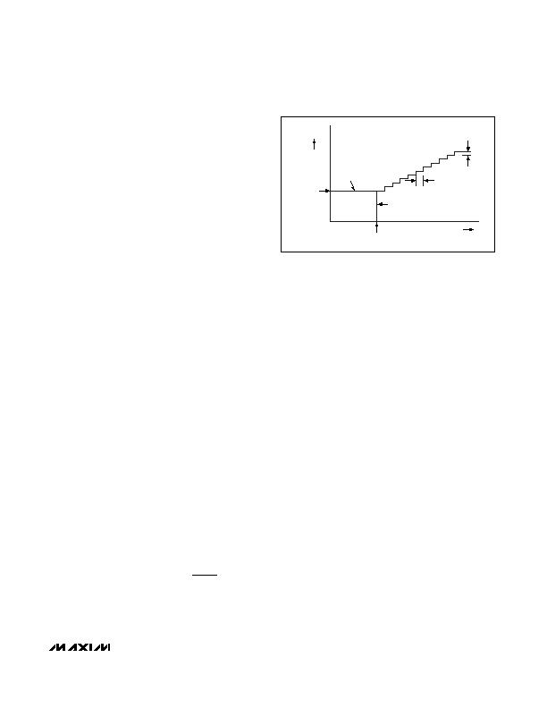
Automatic PWM Duty-Cycle Control
In the automatic control mode, the duty cycle is con-
trolled by the local or remote temperature, according to
the settings in the control registers. Below the value of
the fan-start temperature threshold (set by registers 03h
and 04h), the duty cycle is equal to the fan-start duty
cycle. Above the fan-start temperature, the duty cycle
increases by one duty-cycle step each time the tempera-
ture increases by one temperature step. Below the fan-
start temperature, the duty cycle is either 0% or it is
equal to the fan-start duty cycle, depending on the value
of bit D3 in the configuration byte register. See Figure 8.
The target duty cycle is calculated based on the follow-
ing formula:
For temperature > fan-start temperature:
where:
DC = DutyCycle
FSDC = FanStartDutyCycle
T = Temperature
FST = FanStartTemperature
DCSS = DutyCycleStepSize
TS = TempStep
Duty cycle is recalculated after each temperature con-
version if temperature is increasing. If the temperature
begins to decrease, the duty cycle is not recalculated
until the temperature drops by 5癈 from the last peak
temperature. The duty cycle remains the same until the
temperature drops 5癈 from the last peak temperature
or the temperature rises above the last peak tempera-
ture. For example, if temperature goes up to +85癈 and
starts decreasing, duty cycle is not recalculated until
the temperature reaches +80癈 or the temperature
rises above +85癈. If temperature decreases further,
the duty cycle is not updated until it reaches +75癈.
For temperature < fan-start temperature and bit D3 of
the configuration byte register = 0:
DutyCycle = 0
For temperature < fan-start temperature and bit D3 of
the configuration byte register = 1:
Dutycycle = FanStartDutyCycle
Once the temperature crosses the fan-start tempera-
ture threshold, the temperature has to drop below the
fan-start temperature threshold minus the hysteresis
before the duty cycle returns to either 0% or fan-start
duty cycle. The value of the hysteresis is set by D7 of
the fan-configuration register.
DC FSDC T FST
DCSS
TS
=
+
?/DIV>
(
)
-
FAN START
DUTY CYCLE
TEMPERATURE
DUTY CYCLE
REGISTER 02H,
BIT D3 = 1
DUTY CYCLE
STEP SIZE
FAN START
TEMPERATURE
TEMP
STEP
REGISTER 02H,
BIT D3 = 0
Figure 8. Automatic PWM Duty Control
相關PDF資料 |
PDF描述 |
|---|---|
| MAX6642ATT94+T | IC TEMP SENSOR SMBUS 6TDFN |
| MAX6643LBFAEE+ | IC CTLR PWM FAN-SPEED 16QSOP |
| MAX6649MUA/V+ | IC SENSOR REMOTE SMBUS 8UMAX |
| MAX6652AUB+T | IC TEMP SENS/MON 10-UMAX |
| MAX6659MEE+T | IC TEMP SENSOR SMBUS 16-QSOP |
相關代理商/技術參數 |
參數描述 |
|---|---|
| MAX6641AUB92+ | 功能描述:板上安裝溫度傳感器 SMBus-Compatible Temperature Monitor RoHS:否 制造商:Omron Electronics 輸出類型:Digital 配置: 準確性:+/- 1.5 C, +/- 3 C 溫度閾值: 數字輸出 - 總線接口:2-Wire, I2C, SMBus 電源電壓-最大:5.5 V 電源電壓-最小:4.5 V 最大工作溫度:+ 50 C 最小工作溫度:0 C 關閉: 安裝風格: 封裝 / 箱體: 設備功能:Temperature and Humidity Sensor |
| MAX6641AUB92+T | 功能描述:板上安裝溫度傳感器 SMBus-Compatible Temperature Monitor RoHS:否 制造商:Omron Electronics 輸出類型:Digital 配置: 準確性:+/- 1.5 C, +/- 3 C 溫度閾值: 數字輸出 - 總線接口:2-Wire, I2C, SMBus 電源電壓-最大:5.5 V 電源電壓-最小:4.5 V 最大工作溫度:+ 50 C 最小工作溫度:0 C 關閉: 安裝風格: 封裝 / 箱體: 設備功能:Temperature and Humidity Sensor |
| MAX6641AUB92-T | 功能描述:板上安裝溫度傳感器 RoHS:否 制造商:Omron Electronics 輸出類型:Digital 配置: 準確性:+/- 1.5 C, +/- 3 C 溫度閾值: 數字輸出 - 總線接口:2-Wire, I2C, SMBus 電源電壓-最大:5.5 V 電源電壓-最小:4.5 V 最大工作溫度:+ 50 C 最小工作溫度:0 C 關閉: 安裝風格: 封裝 / 箱體: 設備功能:Temperature and Humidity Sensor |
| MAX6641AUB94 | 功能描述:板上安裝溫度傳感器 RoHS:否 制造商:Omron Electronics 輸出類型:Digital 配置: 準確性:+/- 1.5 C, +/- 3 C 溫度閾值: 數字輸出 - 總線接口:2-Wire, I2C, SMBus 電源電壓-最大:5.5 V 電源電壓-最小:4.5 V 最大工作溫度:+ 50 C 最小工作溫度:0 C 關閉: 安裝風格: 封裝 / 箱體: 設備功能:Temperature and Humidity Sensor |
| MAX6641AUB94+ | 功能描述:板上安裝溫度傳感器 SMBus-Compatible Temperature Monitor RoHS:否 制造商:Omron Electronics 輸出類型:Digital 配置: 準確性:+/- 1.5 C, +/- 3 C 溫度閾值: 數字輸出 - 總線接口:2-Wire, I2C, SMBus 電源電壓-最大:5.5 V 電源電壓-最小:4.5 V 最大工作溫度:+ 50 C 最小工作溫度:0 C 關閉: 安裝風格: 封裝 / 箱體: 設備功能:Temperature and Humidity Sensor |
發布緊急采購,3分鐘左右您將得到回復。