- 您現在的位置:買賣IC網 > Datasheet目錄44 > MAX6642ATT94+T (Maxim Integrated)IC TEMP SENSOR SMBUS 6TDFN Datasheet資料下載
參數資料
| 型號: | MAX6642ATT94+T |
| 廠商: | Maxim Integrated |
| 文件頁數: | 7/14頁 |
| 文件大小: | 154K |
| 描述: | IC TEMP SENSOR SMBUS 6TDFN |
| 產品培訓模塊: | Lead (SnPb) Finish for COTS Obsolescence Mitigation Program |
| 標準包裝: | 2,500 |
| 功能: | 溫度監控系統(傳感器) |
| 傳感器類型: | 內部和外部 |
| 感應溫度: | -40°C ~ 125°C,0°C ~ 150°C |
| 精確度: | ±3°C(最小值) |
| 拓撲: | ADC,多路復用器,寄存器庫 |
| 輸出類型: | I²C?/SMBus? |
| 輸出警報: | 是 |
| 輸出風扇: | 無 |
| 電源電壓: | 3 V ~ 5.5 V |
| 工作溫度: | -40°C ~ 125°C |
| 安裝類型: | 表面貼裝 |
| 封裝/外殼: | 6-WDFN 裸露焊盤 |
| 供應商設備封裝: | 6-TDFN 裸露焊盤(3x3) |
| 包裝: | 帶卷 (TR) |
register was previously selected by a Write Byte
instruction. Use caution when using the shorter proto-
cols in multimaster systems, as a second master could
overwrite the command byte without informing the first
master.
Read temperature data from the read internal tempera-
ture (00h) and read external temperature (01h) regis-
ters. The temperature data format for these registers is
8 bits for each channel, with the LSB representing +1癈
(Table 1).
Read the additional bits from the read extended tem-
perature byte register (10h, 11h), which extends the
data to 10 bits and the resolution to +0.25癈 per LSB
(Table 2).
When a conversion is complete, the main temperature
register and the extended temperature register are
updated.
Alarm Threshold Registers
Two registers store ALERT threshold valuesone each
for the local and remote channels. If either measured
temperature equals or exceeds the corresponding
ALERT threshold value, the ALERT interrupt asserts
unless the ALERT bit is masked.
The power-on-reset (POR) state of the local ALERT
T
HIGH
register is +70癈 (0100 0110). The POR state of
the remote ALERT T
HIGH
register is +120癈 (0111 1000).
Diode Fault Detection
A continuity fault detector at DXP detects an open cir-
cuit on DXP, or a DXP short to V
CC
or GND. If an open
or short circuit exists, the external temperature register
is loaded with 1111 1111 and status bit 2 (OPEN) of the
status byte is set to 1. Immediately after POR, the status
register indicates that no fault is present. If a fault is
present upon power-up, the fault is not indicated until
the end of the first conversion. Diode faults do not set
the ALERT output.
ALERT Interrupts
The ALERT interrupt occurs when the internal or external
temperature reading exceeds a high temperature limit
(user programmed). The ALERT interrupt output signal is
latched and can be cleared only by reading the status
register after the fault condition no longer exists or by
successfully responding to the alert response address. If
?癈, SMBus-Compatible Remote/Local
Temperature Sensor with Overtemperature Alarm
_______________________________________________________________________________________ 7
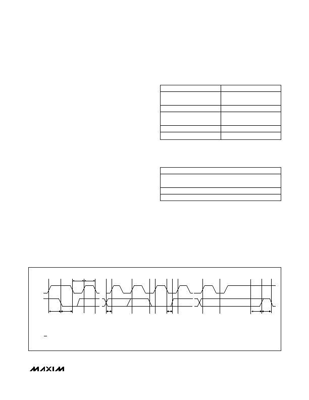
SMBCLK
A
B
C
D
E F
G
H
I
SMBDATA
t
SU:STA
t
HD:STA
t
LOW
t
HIGH
t
SU:DAT
t
HD:DAT
t
SU:STO
t
BUF
A = START CONDITION
B = MSB OF ADDRESS CLOCKED INTO SLAVE
C = LSB OF ADDRESS CLOCKED INTO SLAVE
D = R/W BIT CLOCKED INTO SLAVE
E = SLAVE PULLS SMBDATA LINE LOW
J
K
F = ACKNOWLEDGE BIT CLOCKED INTO MASTER
G = MSB OF DATA CLOCKED INTO MASTER
H = LSB OF DATA CLOCKED INTO MASTER
I = ACKNOWLEDGE CLOCK PULSE
J = STOP CONDITION
K = NEW START CONDITION
Figure 3. SMBus Read Timing Diagram
TEMP (?/SPAN>C)
DIGITAL OUTPUT
130.00
1 000 0010
127.00
0 111 1111
126.00
0 111 1110
25
0 001 1001
0.00
0 000 0000
<0.00
0 000 0000
Diode fault (short or open)
1 111 1111
Table 1. Main Temperature Register
(High Byte) Data Format
FRACTIONAL TEMP (癈)
DIGITAL OUTPUT
0.000
00XX XXXX
0.250
01XX XXXX
0.500
10XX XXXX
0.750
11XX XXXX
Table 2. Extended Resolution
Temperature Register (Low Byte) Data
Format
相關PDF資料 |
PDF描述 |
|---|---|
| MAX6643LBFAEE+ | IC CTLR PWM FAN-SPEED 16QSOP |
| MAX6649MUA/V+ | IC SENSOR REMOTE SMBUS 8UMAX |
| MAX6652AUB+T | IC TEMP SENS/MON 10-UMAX |
| MAX6659MEE+T | IC TEMP SENSOR SMBUS 16-QSOP |
| MAX6661AEE+T | IC REG FAN SPEED 16-QSOP |
相關代理商/技術參數 |
參數描述 |
|---|---|
| MAX6642ATT96+ | 制造商:Maxim Integrated Products 功能描述:- Rail/Tube |
| MAX6642ATT96-T | 功能描述:板上安裝溫度傳感器 RoHS:否 制造商:Omron Electronics 輸出類型:Digital 配置: 準確性:+/- 1.5 C, +/- 3 C 溫度閾值: 數字輸出 - 總線接口:2-Wire, I2C, SMBus 電源電壓-最大:5.5 V 電源電壓-最小:4.5 V 最大工作溫度:+ 50 C 最小工作溫度:0 C 關閉: 安裝風格: 封裝 / 箱體: 設備功能:Temperature and Humidity Sensor |
| MAX6642ATT98 | 制造商:Maxim Integrated Products 功能描述:1 C SMBUS-COMPATIBLE REMOTE/LOCAL TEMPERATURE SENSOR WITH O - Rail/Tube |
| MAX6642ATT98+ | 制造商:Maxim Integrated Products 功能描述:TEMP SENSOR DGTL 2-WIRE 6TDFN EP - Rail/Tube |
| MAX6642ATT98+T | 功能描述:板上安裝溫度傳感器 SMBus-Compatible Temperature Sensor RoHS:否 制造商:Omron Electronics 輸出類型:Digital 配置: 準確性:+/- 1.5 C, +/- 3 C 溫度閾值: 數字輸出 - 總線接口:2-Wire, I2C, SMBus 電源電壓-最大:5.5 V 電源電壓-最小:4.5 V 最大工作溫度:+ 50 C 最小工作溫度:0 C 關閉: 安裝風格: 封裝 / 箱體: 設備功能:Temperature and Humidity Sensor |
發布緊急采購,3分鐘左右您將得到回復。