- 您現在的位置:買賣IC網 > Datasheet目錄44 > MAX6659MEE+T (Maxim Integrated)IC TEMP SENSOR SMBUS 16-QSOP Datasheet資料下載
參數資料
| 型號: | MAX6659MEE+T |
| 廠商: | Maxim Integrated |
| 文件頁數: | 2/16頁 |
| 文件大小: | 165K |
| 描述: | IC TEMP SENSOR SMBUS 16-QSOP |
| 產品培訓模塊: | Lead (SnPb) Finish for COTS Obsolescence Mitigation Program |
| 標準包裝: | 2,500 |
| 功能: | 溫度監控系統(傳感器) |
| 傳感器類型: | 內部和外部 |
| 感應溫度: | -55°C ~ 125°C,外部傳感器 |
| 精確度: | ±5°C(最小值) |
| 拓撲: | ADC,多路復用器,寄存器庫 |
| 輸出類型: | I²C?/SMBus? |
| 輸出警報: | 是 |
| 輸出風扇: | 是 |
| 電源電壓: | 3 V ~ 5.5 V |
| 工作溫度: | -55°C ~ 125°C |
| 安裝類型: | 表面貼裝 |
| 封裝/外殼: | 16-SSOP(0.154",3.90mm 寬) |
| 供應商設備封裝: | 16-QSOP |
| 包裝: | 帶卷 (TR) |
2 _______________________________________________________________________________________
ABSOLUTE MAXIMUM RATINGS
Stresses beyond those listed under
Absolute Maximum Ratings
may cause permanent damage to the device. These are stress ratings only, and functional
operation of the device at these or any other conditions beyond those indicated in the operational sections of the specifications is not implied. Exposure to
absolute maximum rating conditions for extended periods may affect device reliability.
(All voltages referenced to GND.)
V
CC
..........................................................................-0.3V to +6V
DXP ............................................................-0.3V to (V
CC
+ 0.3V)
DXN ......................................................................-0.3V to +0.8V
SMBCLK, SMBDATA, ALERT, OVERT1,
OVERT2 ..............................................................-0.3V to +6V
SMBDATA, ALERT, OVERT1, OVERT2
Current ..........................................................-1mA to +50mA
DXN Current ......................................................................?mA
Continuous Power Dissipation (T
A
= +70癈)
8-Pin SO (derate 5.9mW/癈 above +70癈) .................471mW
16-Pin QSOP (derate 8.3mW/癈 above +70癈) ..........664mW
Junction Temperature .....................................................+150癈
Storage Temperature Range ............................-65癈 to +150癈
Lead Temperature (soldering, 10s) ................................+300癈
Soldering Temperature (reflow)
Lead(Pb)-free ..............................................................+260癈
Containing lead(Pb) ....................................................+240癈
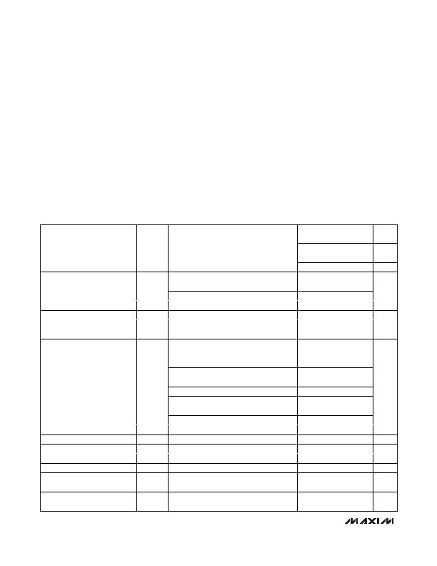
ELECTRICAL CHARACTERISTICS
(V
CC
= +3.0V to +5.5V, T
A
= 0癈 to +125癈, unless otherwise specified. Typical values are at V
CC
= +3.3V and T
A
= +25癈.)
PARAMETER
SYMBOL
CONDITIONS
MIN
TYP
MAX UNITS
1
癈
Temperature Resolution,
Legacy Mode
8
Bits
0.125
癈
Temperature Resolution,
Extended Mode
11
Bits
T
RJ
= +60癈 to +100癈, V
CC
= +3.3V
(Note 1)
-1.0
+1.0
T
RJ
= 0癈 to +100癈, V
CC
= +3.3V (Note 1)
-3.0
+3.0
Remote Temperature Error
(MAX6657, MAX6657Y)
T
RJ
= 0癈 to +125癈, V
CC
= +3.3V (Note 1)
-5.0
+5.0
癈
T
A
= +60癈 to +100癈, V
CC
= +3.3V
-2.0
+2.0
T
A
= 0癈 to +100癈, V
CC
= +3.3V
-3.0
+3.0
Local Temperature Error
(MAX6657)
T
A
= 0癈 to +125癈, V
CC
= +3.3V
-5.0
+5.0
癈
T
RJ
= +60癈 to +100癈, V
CC
= +3.3V
(Note 1)
-1.0
1.0
T
RJ
= 0癈 to +100癈, V
CC
= +3.3V (Note 1)
-3.0
3.0
Remote Temperature Error
(MAX6658/MAX6659/
MAX6658Y/MAX6659Y)
T
RJ
= -55癈 to +125癈, V
CC
= +3.3V (Note 1)
-5.0
+5.0
癈
T
A
= +60癈 to +100癈, V
CC
= +3.3V
-2.0
+2.0
T
A
= 0癈 to +100癈, V
CC
= +3.3V
-3.0
+3.0
Local Temperature Error
(MAX6658/MAX6659)
T
A
= -55癈 to +125癈, V
CC
= +3.3V (Note 2)
-5.0
+5.0
癈
T
A
= +60癈 to +100癈, V
CC
= +3.3V
-3.8
T
A
= 0癈 to +100癈, V
CC
= +3.3V
-4.0
Local Temperature Error
(MAX665_Y)
T
A
= 0癈 to +125癈, V
CC
= +3.3V
-4.4
癈
Line Regulation
3.0V d V
CC
d 5.5V
0.2
0.6
m癈/V
Supply Voltage Range
V
CC
3.0
5.5
V
Undervoltage Lockout Threshold
UVLO
Falling edge of V
CC
disables ADC
2.60
2.80
2.95
V
Undervoltage Lockout Hysteresis
90
mV
Power-On Reset (POR) Threshold
V
CC
, falling edge
1.5
2.0
2.5
V
POR Threshold Hysteresis
90
mV
Standby Supply Current
SMBus static
3
10
礎
Operating Current
During conversion
0.5
1.0
mA
?癈, SMBus-Compatible Remote/Local Temperature
Sensors with Overtemperature Alarms
相關PDF資料 |
PDF描述 |
|---|---|
| MAX6661AEE+T | IC REG FAN SPEED 16-QSOP |
| MAX6664AEE+T | IC TEMP MON FAN CNTRL 16-QSOP |
| MAX6665ASA45+ | IC FAN CNTRL/DRVR 8-SOIC |
| MAX6670AUB45+ | IC TEMP SENSOR REMOTE 10-UMAX |
| MAX6678AEP92+ | IC TEMP MONITOR 2CH PWM 20-QSOP |
相關代理商/技術參數 |
參數描述 |
|---|---|
| MAX665C/D | 功能描述:電荷泵 DICE SALES DICE RoHS:否 制造商:Maxim Integrated 功能:Inverting, Step Up 輸出電壓:- 1.5 V to - 5.5 V, 3 V to 11 V 輸出電流:100 mA 電源電流:1 mA 最大工作溫度:+ 70 C 封裝 / 箱體:SOIC-8 Narrow 封裝:Tube |
| MAX665C/D+ | 功能描述:電荷泵 RoHS:否 制造商:Maxim Integrated 功能:Inverting, Step Up 輸出電壓:- 1.5 V to - 5.5 V, 3 V to 11 V 輸出電流:100 mA 電源電流:1 mA 最大工作溫度:+ 70 C 封裝 / 箱體:SOIC-8 Narrow 封裝:Tube |
| MAX665CPA | 功能描述:電荷泵 RoHS:否 制造商:Maxim Integrated 功能:Inverting, Step Up 輸出電壓:- 1.5 V to - 5.5 V, 3 V to 11 V 輸出電流:100 mA 電源電流:1 mA 最大工作溫度:+ 70 C 封裝 / 箱體:SOIC-8 Narrow 封裝:Tube |
| MAX665CPA+ | 功能描述:直流/直流開關轉換器 8V Switched-Cap Voltage Converter RoHS:否 制造商:STMicroelectronics 最大輸入電壓:4.5 V 開關頻率:1.5 MHz 輸出電壓:4.6 V 輸出電流:250 mA 輸出端數量:2 最大工作溫度:+ 85 C 安裝風格:SMD/SMT |
| MAX665CWE | 功能描述:電荷泵 8V Switched-Cap Voltage Converter RoHS:否 制造商:Maxim Integrated 功能:Inverting, Step Up 輸出電壓:- 1.5 V to - 5.5 V, 3 V to 11 V 輸出電流:100 mA 電源電流:1 mA 最大工作溫度:+ 70 C 封裝 / 箱體:SOIC-8 Narrow 封裝:Tube |
發布緊急采購,3分鐘左右您將得到回復。