- 您現(xiàn)在的位置:買(mǎi)賣(mài)IC網(wǎng) > PDF目錄382301 > MC33121 (Motorola, Inc.) LOW VOLTAGE SUBSCRIBER LOOP INTERFACE CIRCUIT PDF資料下載
參數(shù)資料
| 型號(hào): | MC33121 |
| 廠商: | Motorola, Inc. |
| 英文描述: | LOW VOLTAGE SUBSCRIBER LOOP INTERFACE CIRCUIT |
| 中文描述: | 低電壓用戶環(huán)路接口電路 |
| 文件頁(yè)數(shù): | 21/32頁(yè) |
| 文件大小: | 570K |
| 代理商: | MC33121 |
第1頁(yè)第2頁(yè)第3頁(yè)第4頁(yè)第5頁(yè)第6頁(yè)第7頁(yè)第8頁(yè)第9頁(yè)第10頁(yè)第11頁(yè)第12頁(yè)第13頁(yè)第14頁(yè)第15頁(yè)第16頁(yè)第17頁(yè)第18頁(yè)第19頁(yè)第20頁(yè)當(dāng)前第21頁(yè)第22頁(yè)第23頁(yè)第24頁(yè)第25頁(yè)第26頁(yè)第27頁(yè)第28頁(yè)第29頁(yè)第30頁(yè)第31頁(yè)第32頁(yè)
MC33121
MOTOROLA
21
feedback aspect within this output circuit which provides con-
siderable hysteresis for stability reasons. Its output charac-
teristics are shown in Figures 21 and 22. Due to this
configuration, any external pull–up resistance which is ap-
plied to this pin must be greater than 15 k
, or the output
may not reliably switch from high to low. Any external pull–
down resistance does not affect this output’s ability to switch
from low–to–high, but does affect the maximum longitudinal
currents which can be accepted by the circuit (see the sec-
tion on Longitudinal Current Capability). The capacitor (CT)
is required to provide a time delay, for stability reasons, dur-
ing transitions between off–hook and on–hook. This capaci-
tor additionally affects maximum longitudinal currents, as
well as stability during pulse dialing (explained below).
b) Hook Status
The MC33121 uses the sense currents at CP and CN to
activate the hook status circuit. The sensing is configured
such that the circuit monitors the impedance across Tip/Ring,
which results in the hookswitch thresholds are minimally
affected by the battery voltage. The off–hook to on–hook
threshold is affected by the choice of RRF according to the
graph of Figure 8, but is not affected by the value of RS. The
on–hook to off–hook threshold is affected by the value of RS
according to the graph of Figure 9, but is not affected by RRF.
Varying the RC resistors does not affect the thresholds sig-
nificantly.
When the telephone is on–hook (ST1 = High, ST2 = Low),
the MC33121 is internally powered down, the external tran-
sistors are shut off, and power consumption is at a minimum.
Upon closure of the phone’s hookswitch, ST1 will switch low
within 10
μ
s. ST2 will then change state slowly due to the ex-
ternal capacitor (CT = 5.0
μ
F). There is a
ST2 to reach the threshold necessary to activate the internal
bias circuit, which in turn activates the external drive transis-
tors to supply loop current. This delay is necessary to pre-
vent instabilities during the transition to off–hook.
Upon opening the telephone’s hookswitch, ST1 will switch
high within
200
μ
s. ST2 then requires
the threshold to switch off the internal bias circuit, which in
turn shuts down the external drive transistors.
8.0 ms delay for
60 ms to reach
c) Pulse Dialing
During pulse dialing, ST1 will change state concurrent with
the hookswitch. ST2 is kept from switching during pulse dial-
ing by the external capacitor (CT), which keeps the MC33121
in a powered up condition and stable. If the CT capacitor is
too small, the voltage at ST2 could drop to the PDI threshold
(see section e below) during each pulse. This could cause
the MC33121 to create additional noise on the line as it
would cycle between a power–up and power–down condition
with each dialing pulse.
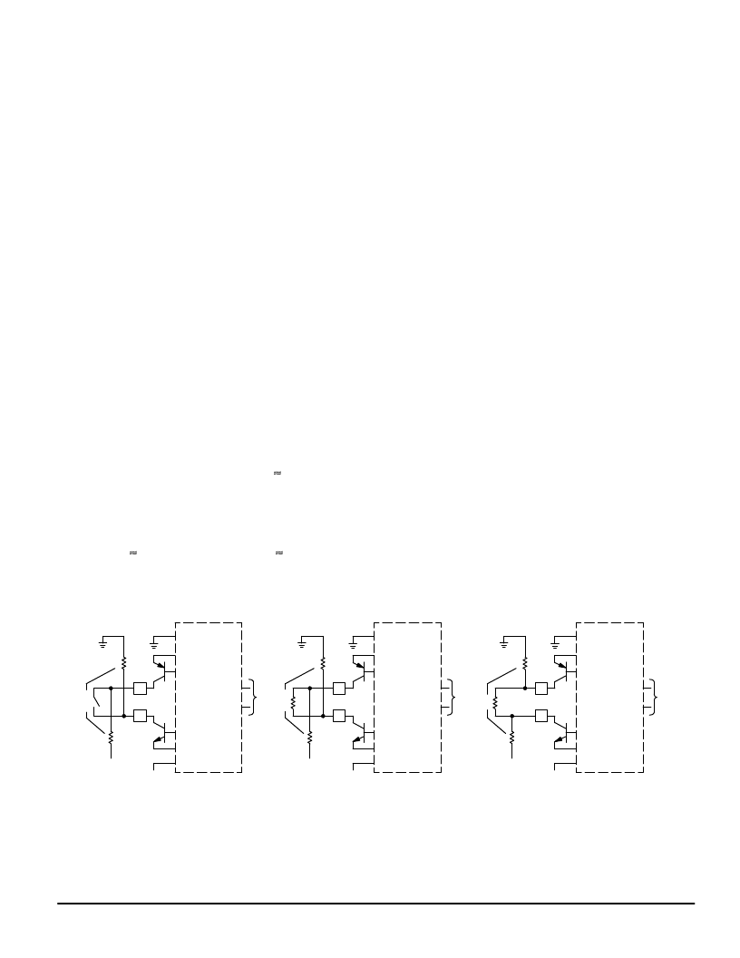
d) Fault Detection
Faults are defined as excessive leakage from Tip to VEE
and/or ground, and from Ring to VEE and/or ground. A single
fault is any one of the above conditions, while a double fault
is defined as excessive leakage from Tip to VEE
and
from
Ring to VCC, as depicted in Figure 38. Refer to Figures 11 –
15 for the resistance, RLK, which will cause the MC33121 to
switch to a power–down condition. If the leakage resistance
is less than that indicated in the graphs, the MC33121 will
power–down itself and the two external transistors, thereby
protecting them from overheating. Both status outputs (ST1
and ST2) will be at a logic low, indicating a fault condition. A
fault condition is detected by monitoring an imbalance in the
magnitudes of the currents at TSI and RSI, and/or a polarity
reversal at Tip and Ring.
The MC33121 will detect the following conditions:
1) When on–hook (see Figure 11):
a) <2.6 k
between Ring and VCC (depending on RS
and VEE), with no hysteresis at this threshold, or
b) <3.7 k
between Tip and VEE (depending on RS
and VEE), with no hysteresis at this threshold, or
c) Both a and b simultaneously.
Leakage from Tip to VCC and/or Ring to VEE are not
detected as faults while the MC33121 is on–hook.
2) When off–hook (367
between Tip and Ring):
a) < 400
between Tip and VCC (RS = 6.2 k
), or
b) < 1800
between Tip and VEE, or
c) < 400
between Ring and VEE (RS = 6.2 k
), or
d) < 1800
between Ring and VCC, or
e) Both b and d simultaneously
Figure 38. Fault Detection
O
ON–HOOK
OFF–HOOK
OFF–HOOK
MC33121
MC33121
MC33121
RLK
VEE
VCC
TIP
RING
ST1
ST2
= 0
RLK
VEE
RLK
VEE
VCC
TIP
RING
ST1
ST2
= 0
RLK
VEE
RLK
VEE
VCC
TIP
RING
ST1
ST2
= 0
RLK
VEE
RL
RL
A
A
相關(guān)PDF資料 |
PDF描述 |
|---|---|
| MC33121FN | LOW VOLTAGE SUBSCRIBER LOOP INTERFACE CIRCUIT |
| MC33121P | LOW VOLTAGE SUBSCRIBER LOOP INTERFACE CIRCUIT |
| MC33151 | High Speed Dual MOSFET Drivers |
| MC33151DR2 | High Speed Dual MOSFET Drivers |
| MC34151DR2 | High Speed Dual MOSFET Drivers |
相關(guān)代理商/技術(shù)參數(shù) |
參數(shù)描述 |
|---|---|
| MC33121FN | 制造商:Motorola Inc 功能描述: |
| MC33121P | 制造商:Rochester Electronics LLC 功能描述:SLIC III - Bulk |
| MC33128 | 制造商:MOTOROLA 制造商全稱(chēng):Motorola, Inc 功能描述:POWER MANAGEMENT CONTROLLER |
| MC33128D | 制造商:MOTOROLA 制造商全稱(chēng):Motorola, Inc 功能描述:POWER MANAGEMENT CONTROLLER |
| MC33129 | 制造商:FREESCALE 制造商全稱(chēng):Freescale Semiconductor, Inc 功能描述:High Performance Current Mode Controllers |
發(fā)布緊急采購(gòu),3分鐘左右您將得到回復(fù)。