- 您現在的位置:買賣IC網 > PDF目錄371048 > MC68HC08MR4 (Motorola, Inc.) In-Circuit Simulator PDF資料下載
參數資料
| 型號: | MC68HC08MR4 |
| 廠商: | Motorola, Inc. |
| 英文描述: | In-Circuit Simulator |
| 中文描述: | 在電路模擬器 |
| 文件頁數: | 72/100頁 |
| 文件大小: | 506K |
| 代理商: | MC68HC08MR4 |
第1頁第2頁第3頁第4頁第5頁第6頁第7頁第8頁第9頁第10頁第11頁第12頁第13頁第14頁第15頁第16頁第17頁第18頁第19頁第20頁第21頁第22頁第23頁第24頁第25頁第26頁第27頁第28頁第29頁第30頁第31頁第32頁第33頁第34頁第35頁第36頁第37頁第38頁第39頁第40頁第41頁第42頁第43頁第44頁第45頁第46頁第47頁第48頁第49頁第50頁第51頁第52頁第53頁第54頁第55頁第56頁第57頁第58頁第59頁第60頁第61頁第62頁第63頁第64頁第65頁第66頁第67頁第68頁第69頁第70頁第71頁當前第72頁第73頁第74頁第75頁第76頁第77頁第78頁第79頁第80頁第81頁第82頁第83頁第84頁第85頁第86頁第87頁第88頁第89頁第90頁第91頁第92頁第93頁第94頁第95頁第96頁第97頁第98頁第99頁第100頁
User
’
s Manual
M68ICS08MR In-Circuit Simulator
72
Using the MON08 Interface
MOTOROLA
Using the MON08 Interface
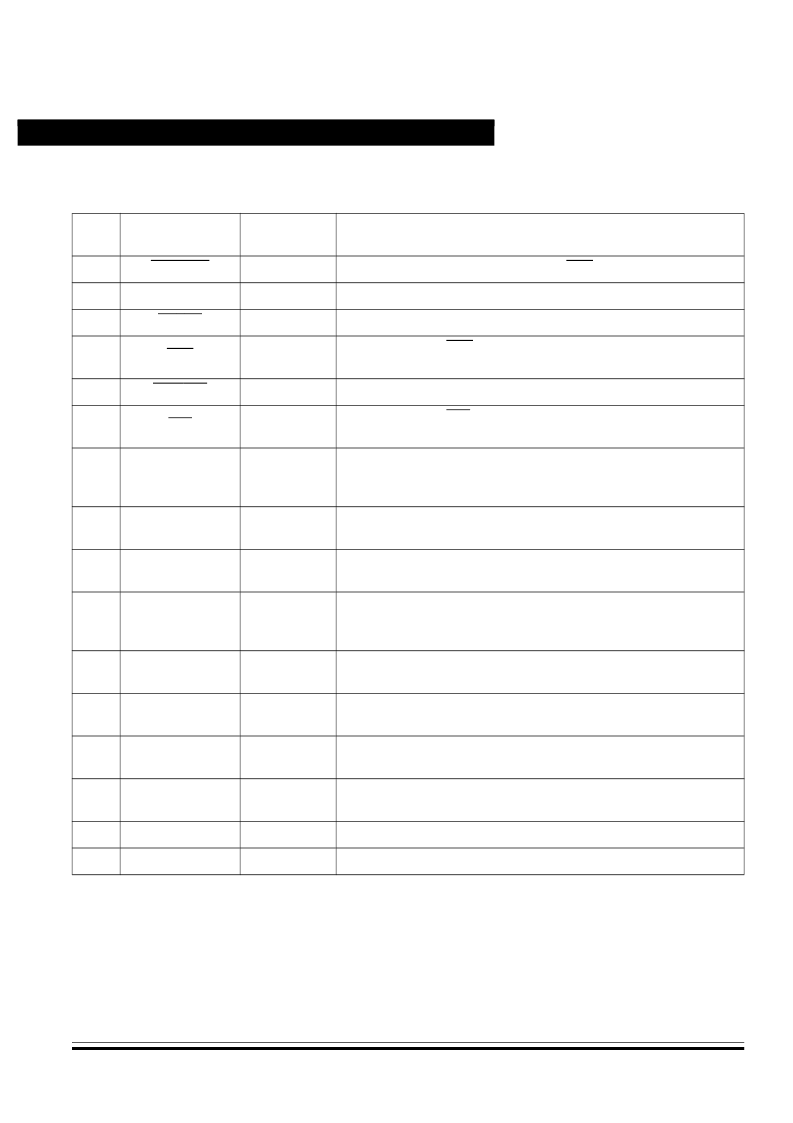
Table 4-1. MR16/32 MON08 Target System Connector J7
Pin
No.
M68ICS08MR
Label
Direction
Target System Connection
1
RST-OUT
Out to target
Connect to logic that is to receive the RST signal.
2
GND
Ground
Connect to ground (V
SS
).
3
RST-IN
In from target
Connect to all logic that generates resets.
4
RST
Bidirectional
Connect to MCU RST pin and P1 pin 1. No other target-system
logic should be tied to this signal. It will swing from 0 to +8.6 Vdc.
5
TGT-IRQ
In from target
Connect to logic that generates interrupts.
6
IRQ
Out to target
Connect to MCU IRQ pin. No other target-system logic should be
tied to this signal. It will swing from 0 to +8.6 Vdc.
7
TGT-PTA0
Bidirectional
Connect to user circuit that would normally be connected to PTA0
on the MCU. This circuit will not be connected to the MCU when
the in-circuit simulator is being used.
8
PTA0
Bidirectional
Connect to MCU PTA0 pin. No other target-system logic should be
tied to this signal. Host I/O present on this pin.
9
TGT-PTB0
Bidirectional
Connect to user circuit that normally would be connected to PTB0
on the MCU.
10
PTB0
Bidirectional
Connect to MCU PTB0 pin. No other target-system logic should be
tied to this signal. Grounded during reset and for 256 cycles after
reset.
11
TGT-PTB2
Bidirectional
Connect to user circuit that normally would be connected to PTB2
on the MCU.
12
PTB2
Bidirectional
Connect to MCU PTB2 pin. No other target-system logic should be
tied to this signal. Held at +5 Vdc during reset.
13
TGT-PTB3
Bidirectional
Connect to user circuit that normally would be connected to PTB3
on the MCU.
14
PTB3
Bidirectional
Connect to MCU PTB3 pin. No other target-system logic should be
tied to this signal. Grounded during reset.
15
NC
NC
Not connected
16
NC
NC
Not connected
相關PDF資料 |
PDF描述 |
|---|---|
| MC68HC11A0CFN2 | HCMOS Single-Chip Microcontroller |
| MC68HC11A8MCFN2 | HCMOS Single-Chip Microcontroller |
| MC68HC11A8BCFN2 | HCMOS Single-Chip Microcontroller |
| MC68HC11A8BCFU2 | HCMOS Single-Chip Microcontroller |
| MC68HC11A8BCP2 | HCMOS Single-Chip Microcontroller |
相關代理商/技術參數 |
參數描述 |
|---|---|
| MC68HC08P4 | 制造商:FREESCALE 制造商全稱:Freescale Semiconductor, Inc 功能描述:HCMOS MICROCONTROLLER UNIT |
| MC68HC08QT1 | 制造商:FREESCALE 制造商全稱:Freescale Semiconductor, Inc 功能描述:M68HC08 Microcontrollers |
| MC68HC08QT2 | 制造商:FREESCALE 制造商全稱:Freescale Semiconductor, Inc 功能描述:M68HC08 Microcontrollers |
| MC68HC08QT4 | 制造商:FREESCALE 制造商全稱:Freescale Semiconductor, Inc 功能描述:M68HC08 Microcontrollers |
| MC68HC08QY1 | 制造商:FREESCALE 制造商全稱:Freescale Semiconductor, Inc 功能描述:M68HC08 Microcontrollers |
發布緊急采購,3分鐘左右您將得到回復。