- 您現(xiàn)在的位置:買賣IC網(wǎng) > PDF目錄371115 > MJE13007 (Electronic Theatre Controls, Inc.) Mini size of Discrete semiconductor elements PDF資料下載
參數(shù)資料
| 型號: | MJE13007 |
| 廠商: | Electronic Theatre Controls, Inc. |
| 英文描述: | Mini size of Discrete semiconductor elements |
| 中文描述: | 迷你型離散半導(dǎo)體元件 |
| 文件頁數(shù): | 1/10頁 |
| 文件大小: | 337K |
| 代理商: | MJE13007 |
1
Motorola Bipolar Power Transistor Device Data
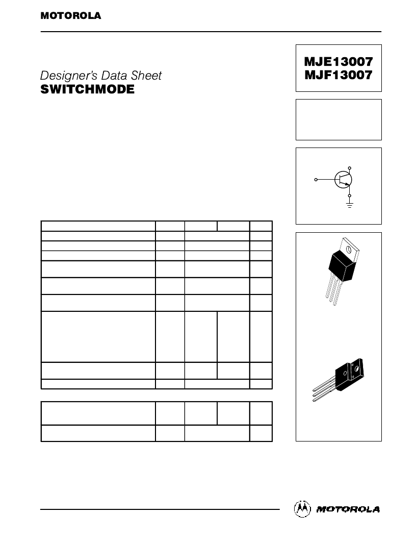
NPN Bipolar Power Transistor
For Switching Power Supply Applications
The MJE/MJF13007 is designed for high–voltage, high–speed power switching
inductive circuits where fall time is critical. It is particularly suited for 115 and 220 V
switchmode applications such as Switching Regulators, Inverters, Motor Controls,
Solenoid/Relay drivers and Deflection circuits.
VCEO(sus) 400 V
Reverse Bias SOA with Inductive Loads @ TC = 100
°
C
700 V Blocking Capability
SOA and Switching Applications Information
Two Package Choices: Standard TO–220 or Isolated TO–220
MJF13007 is UL Recognized to 3500 VRMS, File #E69369
MAXIMUM RATINGS
Rating
Symbol
MJE13007
MJF13007
Unit
Collector–Emitter Sustaining Voltage
VCEO
VCES
VEBO
IC
ICM
IB
IBM
IE
IEM
VISOL
400
Vdc
Collector–Emitter Breakdown Voltage
700
Vdc
Emitter–Base Voltage
9.0
Vdc
Collector Current — Continuous
Collector Current
— Peak (1)
8.0
16
Adc
Base Current — Continuous
Base Current
— Peak (1)
4.0
8.0
Adc
Emitter Current — Continuous
Emitter Current
— Peak (1)
12
24
Adc
RMS Isolation Voltage
(for 1 sec, R.H. < 30%, TA = 25
°
C)
Test No. 1 Per Fig. 15
Test No. 2 Per Fig. 16
Test No. 3 Per Fig. 17
Proper strike and creepage distance must
be provided
—
—
—
4500
3500
1500
V
Total Device Dissipation @ TC = 25
°
C
Derate above 25
°
C
PD
80
0.64
40*
0.32
Watts
W/
°
C
Operating and Storage Temperature
TJ, Tstg
– 65 to 150
°
C
THERMAL CHARACTERISTICS
Thermal Resistance
— Junction to Case
— Junction to Ambient
R
θ
JC
R
θ
JA
°
1.56
°
°
62.5
°
°
3.12
°
°
62.5
°
°
C/W
Maximum Lead Temperature for Soldering
Purposes: 1/8
″
from Case for 5 Seconds
(1) Pulse Test: Pulse Width = 5.0 ms, Duty Cycle
≤
10%.
*Measurement made with thermocouple contacting the bottom insulated mountign surface of the
*
package (in a location beneath the die), the device mounted on a heatsink with thermal grease applied
*
at a mounting torque of 6 to 8
lbs.
TL
260
°
C
Designer’s Data for “Worst Case” Conditions
— The Designer’s Data Sheet permits the design of most circuits entirely from the information presented. SOA Limit
curves — representing boundaries on device characteristics — are given to facilitate “worst case” design.
Designer’s and SWITCHMODE are trademarks of Motorola, Inc.
SEMICONDUCTOR TECHNICAL DATA
Order this document
by MJE13007/D
POWER TRANSISTOR
8.0 AMPERES
400 VOLTS
80/40 WATTS
CASE 221A–06
TO–220AB
MJE13007
CASE 221D–02
ISOLATED TO–220 TYPE
UL RECOGNIZED
MJF13007
相關(guān)PDF資料 |
PDF描述 |
|---|---|
| MJE13007R | Mini size of Discrete semiconductor elements |
| MJE13007 | POWER TRANSISTOR |
| MJF13007 | POWER TRANSISTOR |
| MJF13007 | POWER TRANSISTOR 8.0 AMPERES 400 VOLTS 80/40 WATTS |
| MJE13007 | High Voltage Switch Mode Application |
相關(guān)代理商/技術(shù)參數(shù) |
參數(shù)描述 |
|---|---|
| MJE13007_06 | 制造商:KEC 制造商全稱:KEC(Korea Electronics) 功能描述:TO-220AB PACKAGE |
| MJE13007_08 | 制造商:KEC 制造商全稱:KEC(Korea Electronics) 功能描述:TRIPLE DIFFUSED NPN TRANSISTOR |
| MJE13007_10 | 制造商:UTC-IC 制造商全稱:UTC-IC 功能描述:NPN BIPOLAR POWER TRANSISTOR FOR SWITCHING POWER SUPPLY APPLICATIONS |
| MJE13007A | 功能描述:兩極晶體管 - BJT NPN Hi-Volt Fast Sw RoHS:否 制造商:STMicroelectronics 配置: 晶體管極性:PNP 集電極—基極電壓 VCBO: 集電極—發(fā)射極最大電壓 VCEO:- 40 V 發(fā)射極 - 基極電壓 VEBO:- 6 V 集電極—射極飽和電壓: 最大直流電集電極電流: 增益帶寬產(chǎn)品fT: 直流集電極/Base Gain hfe Min:100 A 最大工作溫度: 安裝風(fēng)格:SMD/SMT 封裝 / 箱體:PowerFLAT 2 x 2 |
| MJE13007D | 制造商:UTC-IC 制造商全稱:UTC-IC 功能描述:NPN BIPOLAR POWER TRANSISTOR FOR SWITCHING POWER SUPPLY APPLICATIONS |
發(fā)布緊急采購,3分鐘左右您將得到回復(fù)。