- 您現在的位置:買賣IC網 > PDF目錄382347 > MR754G (ON SEMICONDUCTOR) High Current Lead Mounted Rectifiers PDF資料下載
參數資料
| 型號: | MR754G |
| 廠商: | ON SEMICONDUCTOR |
| 元件分類: | 參考電壓二極管 |
| 英文描述: | High Current Lead Mounted Rectifiers |
| 中文描述: | 6 A, 400 V, SILICON, RECTIFIER DIODE |
| 封裝: | LEAD FREE, PLASTIC, CASE 194-04, 2 PIN |
| 文件頁數: | 4/7頁 |
| 文件大小: | 104K |
| 代理商: | MR754G |
MR750 SERIES
http://onsemi.com
4
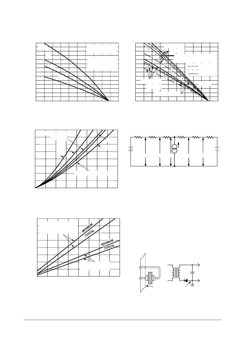
Figure 5. Maximum Current Ratings
T
L
, LEAD TEMPERATURE (
°
C)
0
8.0
I
0
12
20
28
40
80
120
160
200
Figure 6. Maximum Current Ratings
0
8.0
4.0
0
16
24
32
I
F(AV)
, AVERAGE FORWARD CURRENT (AMPS)
Figure 7. Power Dissipation
PF
,
5/8"
,
CAPACITANCE LOADS
8.0
12
16
RESISTIVE INDUCTIVE
LOADS
T
A
, AMBIENT TEMPERATURE (
°
C)
0
1.0
I
0
2.0
3.0
4.0
40
80
120
160
200
Figure 8. Steady State Thermal Resistance
f = 60 Hz
,
RESISTIVE INDUCTIVE LOADS
CAPACITANCE LOADS 1
& 3
20
6
1 & 3
20 I
avg
T
A(A)
T
A(K)
T
L(A)
T
C(A)
T
J
T
C(K)
T
L(K)
P
F
R
S(A)
R
L(A)
R
J(A)
R
J(K)
R
L(K)
R
S(K)
Use of the above model permits junction to lead thermal resistance for
any mounting configuration to be found. Lowest values occur when one
side of the rectifier is brought as close as possible to the heat sink as
shown below. Terms in the model signify:
T
A
= Ambient Temperature
T
L
= Lead Temperature
R
S
= Thermal Resistance, Heat Sink to Ambient
R
L
= Thermal Resistance, Lead to Heat Sink
R
J
= Thermal Resistance, Junction to Case
P
F
= Power Dissipation
(Subscripts A and K refer to anode and cathode sides, respectively.)
Values for thermal resistance components are:
R
L
= 40
°
C/W/in. Typically and 44
°
C/W/in Maximum.
R
J
= 2
°
C/W typically and 4
°
C/W Maximum.
Since R
J
is so low, measurements of the case temperature, T
C
, will be
approximately equal to junction temperature in practical lead mounted
applications. When used as a 60 Hz rectifierm the slow thermal response
holds T
J(PK)
close to T
J(AVG)
. Therefore maximum lead temperature may
be found from: T
L
= 175
R
JL
P
F
. P
F
may be found from Figure 7.
The recommended method of mounting to a P.C. board is shown on the
sketch, where R
JA
is approximately 25
°
C/W for a 11/2" x 11/2" copper
surface area. Values of 40
°
C/W are typical for mounting to terminal strips
or P.C. boards where available surface area is small.
T
C
= Case Temperature
T
J
= Junction Temperature
éé
éé
éé
éé
éé
éé
éé
Board Ground Plane
24
28
32
0
1/4
5.0
0
1/2
3/4
1.0
L, LEAD LENGTH (INCHES)
θ
SINGLE LEAD TO HEAT SINK,
INSIGNIFICANT HEAT FLOW
THROUGH OTHER LEAD
10
15
20
25
30
35
40
24
16
4.0
20
60
100
140
180
4.0
12
20
28
1/8
3/8
5/8
7/8
J
°
BOTH LEADS TO HEAT
SINK WITH LENGTHS
AS SHOWN
3/8"
1/4"
L = 1/8"
20
60
100
140
180
5.0
6.0
7.0
I
(pk)
= 5 I
avg
I
(pk)
= 10 I
avg
I
(pk)
= 20 I
avg
10 I
avg
I
(pk)
= 5 I
avg
RESISTIVE INDUCTIVE LOADS
BOTH LEADS TO HEAT
SINK, EQUAL LENGTH
6 (I
PK
/I
AVE
= 6.28)
SEE NOTE
R
JA
= 40
°
C/W
SEE NOTE
R
JA
= 25
°
C/W
NOTES
THERMAL CIRCUIT MODEL
(For Heat Conduction Through The Leads)
相關PDF資料 |
PDF描述 |
|---|---|
| MR754RL | High Current Lead Mounted Rectifiers |
| MR754RLG | High Current Lead Mounted Rectifiers |
| MR756G | High Current Lead Mounted Rectifiers |
| MR756RL | High Current Lead Mounted Rectifiers |
| MR756RLG | High Current Lead Mounted Rectifiers |
相關代理商/技術參數 |
參數描述 |
|---|---|
| MR754G | 制造商:ON Semiconductor 功能描述:Fast Recovery Power Rectifier |
| MR754RL | 功能描述:整流器 400V 6A Silicon RoHS:否 制造商:Vishay Semiconductors 產品:Standard Recovery Rectifiers 配置: 反向電壓:100 V 正向電壓下降: 恢復時間:1.2 us 正向連續電流:2 A 最大浪涌電流:35 A 反向電流 IR:5 uA 安裝風格:SMD/SMT 封裝 / 箱體:DO-221AC 封裝:Reel |
| MR754RLG | 功能描述:整流器 400V 6A Silicon RoHS:否 制造商:Vishay Semiconductors 產品:Standard Recovery Rectifiers 配置: 反向電壓:100 V 正向電壓下降: 恢復時間:1.2 us 正向連續電流:2 A 最大浪涌電流:35 A 反向電流 IR:5 uA 安裝風格:SMD/SMT 封裝 / 箱體:DO-221AC 封裝:Reel |
| MR754-T3 | 制造商:WTE 制造商全稱:Won-Top Electronics 功能描述:6.0A STANDARD DIODE |
| MR756 | 功能描述:整流器 600V 6A Silicon RoHS:否 制造商:Vishay Semiconductors 產品:Standard Recovery Rectifiers 配置: 反向電壓:100 V 正向電壓下降: 恢復時間:1.2 us 正向連續電流:2 A 最大浪涌電流:35 A 反向電流 IR:5 uA 安裝風格:SMD/SMT 封裝 / 箱體:DO-221AC 封裝:Reel |
發布緊急采購,3分鐘左右您將得到回復。