- 您現在的位置:買賣IC網 > PDF目錄374495 > MR850 (MOTOROLA INC) FAST RECOVERY POWER RECTIFIERS 50.600 VOLTS 3.0 AMPERES PDF資料下載
參數資料
| 型號: | MR850 |
| 廠商: | MOTOROLA INC |
| 元件分類: | 參考電壓二極管 |
| 英文描述: | FAST RECOVERY POWER RECTIFIERS 50.600 VOLTS 3.0 AMPERES |
| 中文描述: | 3 A, 50 V, SILICON, RECTIFIER DIODE |
| 文件頁數: | 1/2頁 |
| 文件大小: | 134K |
| 代理商: | MR850 |
MR850 THRU MR856
SOFT RECOVERU, FAST SWITCHING PLASTIC RECTIFIER
VOLTAGE - 50 to 600 Volts CURRENT - 3.0 Amperes
FEATURES
l
High surge current capability
l
Plastic package has Underwriters Laboratory
Flammability Classification 94V-O
l
Void-free molded plastic package
l
3.0 ampere operation at T
A
=50
with no thermal runaway
l
Exceeds environmental standards of MIL-S-19500/228
l
Fast switching for high efficiency
MECHANICAL DATA
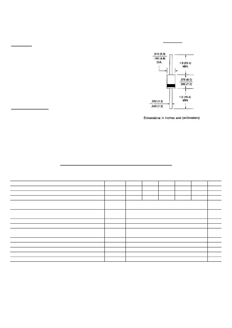
Case: JEDEC DO-201AD molded plastic
Terminals: Plated Axial leads, solderable per MIL-STD-750,
Method 2026
Polarity: Color Band denotes end
Mounting Position: Any
Weight: 0.04 ounce, 1.1 gram
MAXIMUM RATINGS AND ELECTRICAL CHARACTERISTICS
Ratings at 25
ambient temperature unless otherwise specified.
Resistive or inductive load.
Maximum Recurrent Peak Reverse Voltage
Maximum RMS Voltage
Maximum DC Blocking Voltage
Maximum Average Forward Rectified Current
.375"(9.5mm) Lead Length at T
A
=50
Peak Forward Surge Current 10ms single half sine-
wave superimposed on rated load at T
A
=25
Maximum Repetitive Peak Forward Surge(Note1)
Maximum Instantaneous Forward Voltage at 3.0A
Maximum DC Reverse Current T
A
=25
at Rated DC Blocking Voltage T
A
=100
Maximum Reverse Recovery Time(Note 3) T
J
=25
Typical Junction capacitance (Note 2)
Typical Thermal Resistance (Note 4)
Operating Junction Temperature Range
Storage Temperature Range
SYMBOLS MR850 MR851 MR852 MR854 MR856 UNITS
V
RRM
50
100
200
V
RMS
35
70
140
V
DC
50
100
200
I
(AV)
400
280
400
600
480
600
Volts
Volts
Volts
Amps
3.0
I
FSM
100.0
Amps
I
FRM
V
F
I
R
10.0
1.25
10.0
500.0
150
60
15.0
-50 to +125
-50 to +150
Amps
Volts
A
A
ns
P
F
/W
T
RR
C
J
R
JA
T
J
T
STG
NOTES:
1. Repetitive Peak Forward Surge Current at f<15KHz
2.
Measured at 1 MHz and applied reverse voltage of 4.0 Volts
3.
Reverse Recovery Test Conditions: I
F
=0.5A, I
R
=1.0A, I
rr
=0.25A
4.
Thermal Resistance From Junction to Ambient at 0.375"(9.5mm) lead length with both leads to heat sink
DO-201AD
相關PDF資料 |
PDF描述 |
|---|---|
| MR851 | FAST RECOVERY POWER RECTIFIERS 50.600 VOLTS 3.0 AMPERES |
| MR850 | FAST RECOVERY RECTIFIER DIODES |
| MR851 | FAST RECOVERY RECTIFIER DIODES |
| MR851 | SOFT RECOVERU, FAST SWITCHING PLASTIC RECTIFIER |
| MR850 | 3.0 AMP FAST RECOVERY RECTIFIERS |
相關代理商/技術參數 |
參數描述 |
|---|---|
| MR850 _AY _10001 | 制造商:PanJit Touch Screens 功能描述: |
| MR850 R0 | 制造商:SKMI/Taiwan 功能描述:Diode Switching 50V 3A 2-Pin DO-201AD T/R |
| MR850_ R2 _10001 | 制造商:PanJit Touch Screens 功能描述: |
| MR850_09 | 制造商:PANJIT 制造商全稱:Pan Jit International Inc. 功能描述:SOFT RECOVERY, FAST SWITCHING PLASTIC RECTIFIER |
| MR850G | 制造商:ON Semiconductor 功能描述:Diode Switching 50V 3A 2-Pin Case 267-05 Box 制造商:ON Semiconductor 功能描述:REC AXIAL 3A 50V FST - Bulk |
發布緊急采購,3分鐘左右您將得到回復。