- 您現在的位置:買賣IC網 > PDF目錄98035 > MRF1027T1 (MOTOROLA INC) UHF BAND, Si, NPN, RF SMALL SIGNAL TRANSISTOR PDF資料下載
參數資料
| 型號: | MRF1027T1 |
| 廠商: | MOTOROLA INC |
| 元件分類: | 小信號晶體管 |
| 英文描述: | UHF BAND, Si, NPN, RF SMALL SIGNAL TRANSISTOR |
| 封裝: | PLASTIC, SC-70, 3 PIN |
| 文件頁數: | 1/12頁 |
| 文件大?。?/td> | 217K |
| 代理商: | MRF1027T1 |
RF NPN
SILICON TRANSISTOR
f
τ = 12 GHz
NFmin = 1.0 dB
ICMAX = 25 mA
VCEO = 5.0 V
MRF1027T1
SEMICONDUCTOR
TECHNICAL DATA
Order this document by MRF1027T1/D
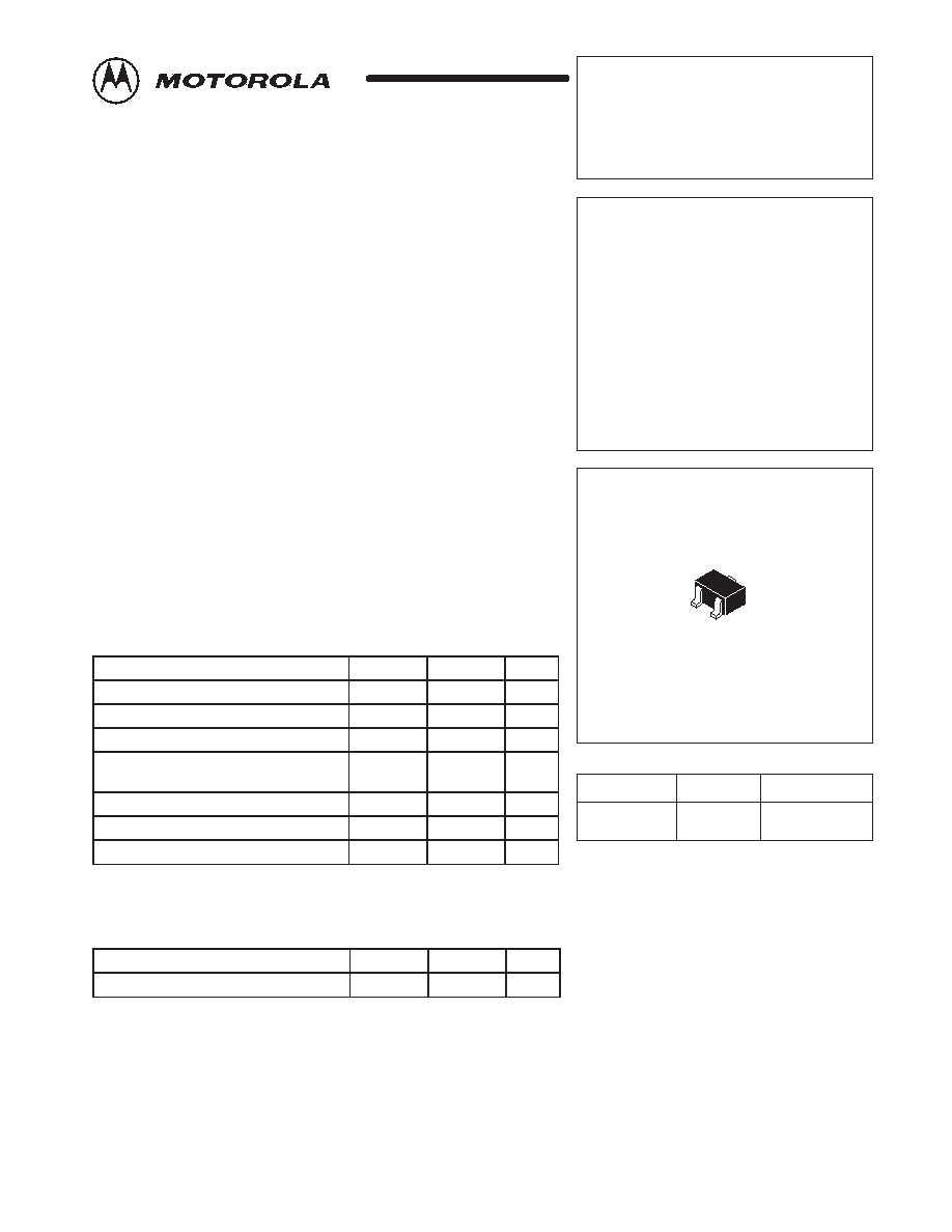
PLASTIC PACKAGE
CASE 419
(SC–70, Tape & Reel Only)
3
1
Pin 1. Base
2. Emitter
3. Collector
2
ORDERING INFORMATION
Device
Package
MRF1027T1
SC–70
Tape & Reel*
Marking
WA
*3,000 Units per 8 mm, 7 inch reel.
1
MOTOROLA RF/IF DEVICE DATA
Advance Information
NPN Silicon
Low Noise Transistor
The MRF1027T1 is fabricated utilizing Motorola’s latest 12 GHz f
τ discrete
bipolar silicon process. It offers 1.0 dB Minimum Noise Figure at VCE = 1.0 V,
IC = 1.0 mA and f = 1.0 GHz. The noise performance of the MRF1027T1 at
low bias makes this device the ideal choice in high gain, low noise
applications. This device is well suited for low–voltage, low–current,
front–end applications. It is designed for use in pagers, cellular and cordless
phones, and other portable wireless systems.
The MRF1027T1 has 9 emitter fingers, with self–aligned and enhanced
processing; resulting in a high f
τ, low operating current transistor with
reduced parasitics. The MRF1027T1 is fully–ion implanted with gold
metallization and nitride passivation for maximum device reliability,
performance and uniformity.
Low Noise Figure, NFmin = 1.0 dB (Typ) @1.0 GHz, 3.0 V and 1.0 mA
High Current Gain–Bandwidth Product, fτ = 12 GHz @ 3.0 V and 10 mA
Maximum Stable Gain, 17 dB @ 1.0 GHz, 3.0 V and 8.0 mA
Output Third Order Intercept, OIP3 = 23 dBm @ 1.0 GHz, 3.0 V and
10 mA
Fully Ion–Implanted with Gold Metallization and Nitride Passivation
MAXIMUM RATINGS
Rating
Symbol
Value
Unit
Collector–Emitter Voltage
VCEO
5.0
Vdc
Collector–Base Voltage
VCBO
12
Vdc
Emitter–Base Voltage
VEBO
2.5
Vdc
Power Dissipation @ TC=75°C
PD(max)
136
W
Derate Linearly above TC = 75°C at
1.82
mW/
°C
Collector Current–Continuous [Note 3]
IC
25
mA
Maximum Junction Temperature
TJ(max)
150
°C
Storage Temperature
Tstg
–55 to 150
°C
NOTES: 1. Meets Human Body Model (HBM)
≤300 V and Machine Model (MM) ≤75 V.
2. ESD data available upon request.
3. IC Continuous for MTBF >10 years.
THERMAL CHARACTERISTIC
Characteristics
Symbol
Max
Unit
Thermal Resistance, Junction–to–Case
R
θJC
550
°C/W
NOTE:
To calculate the junction temperature use TJ = (PD x R
θJC) + TC. The case
temperature measured on collector lead adjacent to the package body.
This document contains information on a new product. Specifications and information herein
are subject to change without notice.
Motorola, Inc. 1998
Rev 1
LIFETIME
BUY
L
A
S
T
O
R
D
E
R
1
7
S
E
P
0
L
A
S
T
S
H
IP
1
7
M
A
R
0
1
相關PDF資料 |
PDF描述 |
|---|---|
| MRF1047T1 | UHF BAND, Si, NPN, RF SMALL SIGNAL TRANSISTOR |
| MRF1057T1 | UHF BAND, Si, NPN, RF SMALL SIGNAL TRANSISTOR |
| MRF136Y | 2 CHANNEL, UHF BAND, Si, N-CHANNEL, RF POWER, MOSFET |
| MRF136 | UHF BAND, Si, N-CHANNEL, RF POWER, MOSFET |
| MRF1507T1 | UHF BAND, Si, N-CHANNEL, RF POWER, MOSFET |
相關代理商/技術參數 |
參數描述 |
|---|---|
| MRF1030 | 制造商:MOTOROLA 制造商全稱:Motorola, Inc 功能描述:UHF POWER TRANSISTOR |
| MRF1031 | 制造商:MOTOROLA 制造商全稱:Motorola, Inc 功能描述:UHF POWER TRANSISTOR |
| MRF1035 | 制造商:MA-COM 制造商全稱:M/A-COM Technology Solutions, Inc. 功能描述:MICROWAVE POWER TRANSISTOR NPN SILICON |
| MRF10350 | 制造商:M/A-COM Technology Solutions 功能描述:RF POWER TRANSISTOR BIPOLAR/HBT |
| MRF1035MB | 制造商:MOTOROLA 制造商全稱:Motorola, Inc 功能描述:MICROWAVE POWER TRANSISTORS |
發布緊急采購,3分鐘左右您將得到回復。