- 您現在的位置:買賣IC網 > PDF目錄382351 > MSS2101 (Mosel Vitelic, Corp.) 21" Voice ROM with Supply CPU,KBD,MTX Addressing Interface Modes for Versatile Applications(為各種用途而提供的CPU,KBD和MTX地址接口模式的話音ROM) PDF資料下載
參數資料
| 型號: | MSS2101 |
| 廠商: | Mosel Vitelic, Corp. |
| 英文描述: | 21" Voice ROM with Supply CPU,KBD,MTX Addressing Interface Modes for Versatile Applications(為各種用途而提供的CPU,KBD和MTX地址接口模式的話音ROM) |
| 中文描述: | 21供應的CPU,大骨節病,呤“語音解決光盤應用的通用接口模式(為各種用途而提供的處理器,大骨節病和甲氨喋呤地址接口模式的話音光盤) |
| 文件頁數: | 2/12頁 |
| 文件大小: | 87K |
| 代理商: | MSS2101 |
MSS2101/S3201
MOSEL VITELIC INC.
2/10
PID 227(B) 04/95
Specifications subject to change without notice, contact your sales representatives for the most recent information.
Pad Description
Pad No.
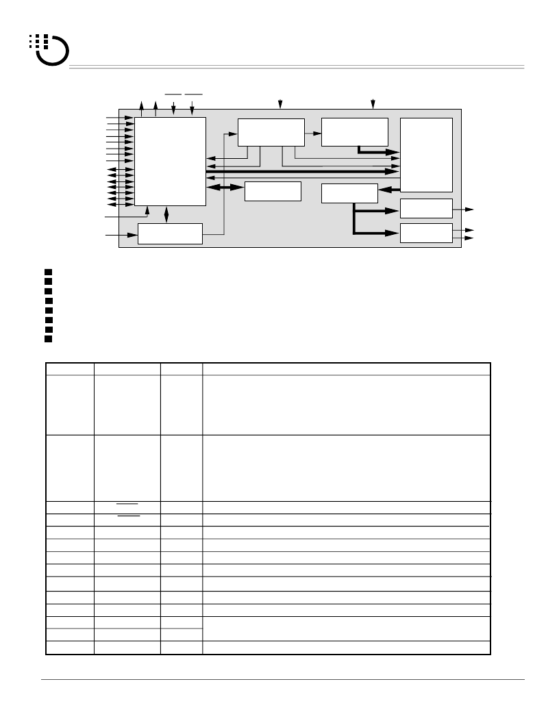
Block Diagram
Mask option for
either Level or Edge trigger type for MTX and KBD modes.
either Holdable or unholdable output type for MTX and KBD modes.
either retriggerable or not for all 3 modes.
either BUSY signal or STOP pulse output on BS output.
either low or high active for STOP pulse output.
random or playall or playnext (sequential ) output on OKY (one key) input pin.
either return to the 1st section(ORIGINAL)or keep continuing (CURRENT) for PLAYNEXT (sequential) function.
3 addressing interface modes.
CLOCK
GENERATOR
CONTROL
LOGIC
BS
ROW0
ROW1
ROW2
ROW3
ROW4
ROW5
ROW6
OSC
TIMING
GENERATOR
ADDRESS
GENERATOR
TRIGGER
TABLE
MPCM
DECODER
VOICE
ROM
SPEAKER
BUFFER
BUZZER
BUFFER
COUT
VOUT1
VOUT2
VDD
VSS
TG0
TG1
TG2
TG3
TG4
TG5
TG6
TG7
INTP OKY
LED
CHG
Signal Name
Function
7~13
14
15
16
V
DD
OSC
V
SS
V
OUT2
BS
V
OUT1
Positive power supply
Oscillator Resistor input
Negative power supply
I/O
O
Power
I
C
OUT
Power
O
O
O
19
20
17
18
CPU mode: No connection.
KBD mode: with TG0 ~ TG7 for trigger input,
internal pull high, active low.
ROW0~ROW4 are used as Decimal digit (D-tree)
ROW5 and ROW6 are used for S-tree.
MTX mode: with TG0 ~ TG7 for scanning function,
used as output pins.
Interrupt, stops the audio output at once;low active.
Audio signal voltage output (for buzzer)
Audio signal current output (for speaker)
ROW6~ROW0
CHG
NC
Busy / Stop
NC/I/O
NC
NC: No connection
21
22
23
24
25
TG0
I
1~6
TG7
CPU mode: address input (TG0 ~ TG6), internal pull high,
negative strobe trigger (TG7).
KBD mode: with ROW0 ~ROW6 for trigger input,
internal pull high, active low.
MTX mode: with ROW0 ~ROW6 for scanning function,
internal pull high, active low.
26,27
OKY
LED
INTP
I
I
One key Play, playall or playnext or random-play;active low.
LED, sink current
Change addressing interface mode from existing mode
O
I
~
相關PDF資料 |
PDF描述 |
|---|---|
| MSS3201 | 32" Voice ROM with Supply CPU,KBD,MTX Addressing Interface Modes for Versatile Applications(為各種用途而提供的CPU,KBD和MTX地址接口模式的話音ROM) |
| MSS3205 | 32 Voice ROM |
| MSS6605 | 21/32/43/60 VOICE ROM |
| MSSI121-2 | 12 Instant Voice VROM |
| MSU2955 | 8-Bit Micro-controller |
相關代理商/技術參數 |
參數描述 |
|---|---|
| MSS2105 | 制造商:MOSEL 制造商全稱:MOSEL 功能描述:21/32/43/60 VOICE ROM |
| MSS2105-1 | 制造商:MOSEL 制造商全稱:MOSEL 功能描述:21/32/43/60 VOICE ROM |
| MSS21505A | 制造商:未知廠家 制造商全稱:未知廠家 功能描述:DIP 14 SERIES REED RELAYS |
| MSS21505B | 制造商:未知廠家 制造商全稱:未知廠家 功能描述:DIP 14 SERIES REED RELAYS |
| MSS21505C | 制造商:未知廠家 制造商全稱:未知廠家 功能描述:DIP 14 SERIES REED RELAYS |
發布緊急采購,3分鐘左右您將得到回復。