- 您現在的位置:買賣IC網 > PDF目錄382352 > MTC20136 (意法半導體) ADSL TRANSCEIVER CONTROLLER PDF資料下載
參數資料
| 型號: | MTC20136 |
| 廠商: | 意法半導體 |
| 英文描述: | ADSL TRANSCEIVER CONTROLLER |
| 中文描述: | 寬帶收發器控制器 |
| 文件頁數: | 16/25頁 |
| 文件大小: | 634K |
| 代理商: | MTC20136 |
MTC20136
16/25
EBI Interface Timing
All timing parameters are specified at a load of 100 pF, all the electrical levels are CMOS compatible.
Table 2. All signals
Table 3. EBI signal timing with respect to E_CLK
CTRLE
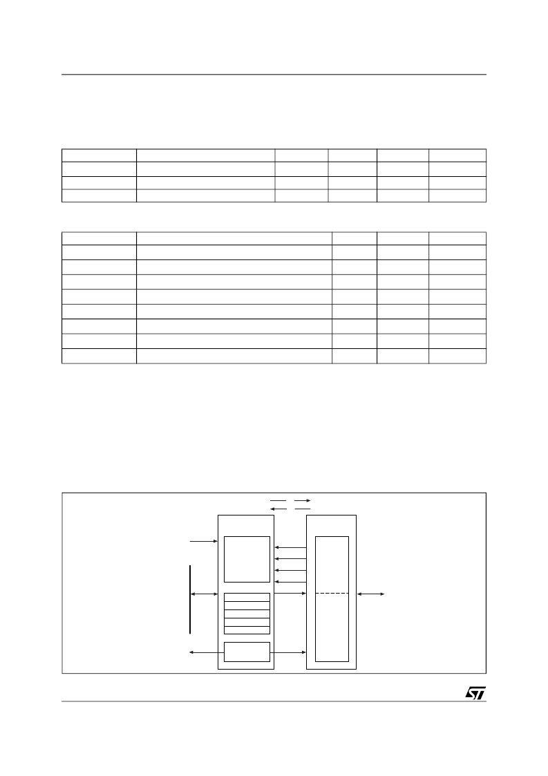
The Ctrl-E interface is an ADSL-oriented mailbox system to exchange control and status messages be-
tween MTC20136 and an external controller. It consists of a mailbox and a physical interface. The mailbox
has two 8-bit command registers to pass commands from the MTC20136 internal controller bus (ASB) to
Ctrl-E (RxCommand) and from Ctrl-E to ASB (TxCommand), and two status registers (RxComAv and Tx-
ComAv) to indicate the status of the command register. Data associated with a command can be ex-
changed using a common CtrleDataBuffer. A hardware semaphore mechanism is provided to allow
control of data consistency of the CtrleDataBuffer.
Figure 7. Ctrl-E interface controller principle
Symbol
Parameters
Min
Typ
Max
3
Unit
ns
t
r
,t
f
Ci
Co
Rise and Fall time (10% - 90%)
Input load
Output load
10
100
pF
pF
Symbol
Parameters
Min
3
Max
Unit
ns
T
dh
Data input hold time from E_CLK
T
ds
Data input setup time to E_CLK
10
ns
T
dd
Data/Address output valid/tri-state delay from E_CLK
10
ns
T
wrd
ALE delay from E_CLK
6
ns
T
oed
notOE delay from E_CLK
6
ns
T
wed
notWEi delay from E_CLK (falling edge)
6
ns
T
wrd
W/notR delay from E_CLK
3
10
ns
T
csd
notCSi delay from E_CLK
3
10
ns
Ctrl-E
physical interface
Ctrl-E
Mailbox
CtrleDataBuffer
(512*8 bit
dual port RAM)
Semaphore
RxComAv
TxComAv
RxCommand
TxCommand
Mailbox Interrupt
controller
Ctrl-E
Serial
Interface
Generic
Parallel
Interface
TX
RX
D_SELctrle
I/O
MRd
MWr
MA[8:0]
MD[7:0]
MQ[7:0]
Ctrlelnt1
Ctrlelnt0
ASB
To IT-
Controller
相關PDF資料 |
PDF描述 |
|---|---|
| MTC20136MB-I1 | ADSL TRANSCEIVER CONTROLLER |
| MTC20136PQ-l1 | ADSL TRANSCEIVER CONTROLLER |
| MTC50150 | ADSL GATEWAY PROCESSOR |
| MTC50150-TB-C2 | ADSL GATEWAY PROCESSOR |
| MTD10N10ELT4G | TMOS E−FET Power Field Effect Transistor DPAK for Surface Mount |
相關代理商/技術參數 |
參數描述 |
|---|---|
| MTC20136-MB-I1 | 制造商:STMicroelectronics 功能描述: |
| MTC20136MB-I1 | 制造商:STMICROELECTRONICS 制造商全稱:STMicroelectronics 功能描述:ADSL TRANSCEIVER CONTROLLER |
| MTC20136-PQ-I1 | 制造商:STMicroelectronics 功能描述:ADSL TRNSCVR CNTRLR 144PQFP - Trays |
| MTC20136-PQ-IL | 制造商:STMicroelectronics 功能描述: |
| MTC20136PQ-L1 | 制造商:STMICROELECTRONICS 制造商全稱:STMicroelectronics 功能描述:ADSL TRANSCEIVER CONTROLLER |
發布緊急采購,3分鐘左右您將得到回復。