- 您現在的位置:買賣IC網 > PDF目錄382356 > MZP4753A (ON SEMICONDUCTOR) 3 Watt DO-41 Surmetic 30 Zener Voltage Regulators PDF資料下載
參數資料
| 型號: | MZP4753A |
| 廠商: | ON SEMICONDUCTOR |
| 元件分類: | 參考電壓二極管 |
| 英文描述: | 3 Watt DO-41 Surmetic 30 Zener Voltage Regulators |
| 中文描述: | 36 V, 1 W, SILICON, UNIDIRECTIONAL VOLTAGE REGULATOR DIODE, DO-41 |
| 封裝: | PLASTIC, CASE 59-10, 2 PIN |
| 文件頁數: | 3/8頁 |
| 文件大小: | 57K |
| 代理商: | MZP4753A |
MZP4729A Series
http://onsemi.com
3
ELECTRICAL CHARACTERISTICS
(T
A
= 25
°
C unless otherwise noted, V
F
= 1.5 V Max @ I
F
= 200 mA for all types)
Zener Voltage
(Note 2)
Zener Impedance
(Note 3)
Leakage Current
I
R
Device
(Note 1)
Device
Marking
V
Z
(Volts)
@ I
ZT
Z
ZT
@ I
ZT
Z
ZK
@ I
ZK
I
R
@ V
R
(Note 4)
Min
Nom
Max
mA
mA
μ
A Max
Volts
mA
MZP4729A
MZP4734A
MZP4735A
MZP4736A
MZP4737A
MZP4729A
MZP4734A
MZP4735A
MZP4736A
MZP4737A
3.42
5.32
5.89
6.46
7.13
3.6
5.6
6.2
6.8
7.5
3.78
5.88
6.51
7.14
7.88
69
45
41
37
34
10
5
2
3.5
4
400
600
700
700
700
1
1
1
1
100
10
10
10
10
1
2
3
4
5
1260
810
730
660
605
0.5
MZP4738A
MZP4740A
MZP4741A
MZP4744A
MZP4745A
MZP4738A
MZP4740A
MZP4741A
MZP4744A
MZP4745A
7.79
9.50
10.45
14.25
15.20
8.2
10
11
15
16
8.61
10.50
11.55
15.75
16.80
31
25
23
17
15.5
4.5
7
8
14
16
700
700
700
700
700
0.5
0.25
0.25
0.25
0.25
10
10
5
5
5
6
550
454
414
304
285
7.6
8.4
11.4
12.2
MZP4746A
MZP4749A
MZP4750A
MZP4751A
MZP4752A
MZP4746A
MZP4749A
MZP4750A
MZP4751A
MZP4752A
17.10
22.80
25.65
28.50
31.35
18
24
27
30
33
18.90
25.20
28.35
31.50
34.65
14
10.5
9.5
8.5
7.5
20
25
35
40
45
750
750
750
1000
1000
0.25
0.25
0.25
0.25
0.25
5
5
5
5
5
13.7
18.2
20.6
22.8
25.1
250
190
170
150
135
MZP4753A
1.
TOLERANCE AND TYPE NUMBER DESIGNATION
The type numbers listed have a standard tolerance on the nominal zener voltage of
±
5%.
2.
ZENER VOLTAGE (V
) MEASUREMENT
ON Semiconductor guarantees the zener voltage when measured at 90 seconds while maintaining the lead temperature (T
L
) at 30
°
C
±
1
°
C,
3/8
″
from the diode body.
3.
ZENER IMPEDANCE (Z
) DERIVATION
The zener impedance is derived from 60 seconds AC voltage, which results when an AC current having an rms value equal to 10% of the
DC zener current (I
ZT
or I
ZK
) is superimposed on I
ZT
or I
ZK
.
4.
SURGE CURRENT (I
R
) NON–REPETITIVE
The rating listed in the electrical characteristics table is maximum peak, non–repetitive, reverse surge current of 1/2 square wave or
equivalent sine wave pulse of 1/120 second duration superimposed on the test current, I
ZT
, per JEDEC standards. However, actual device
capability is as described in Figure 3 of the General Data sheet for Surmetic 30s.
MZP4753A
34.20
36
37.80
7.0
50
1000
0.25
5
27.4
125
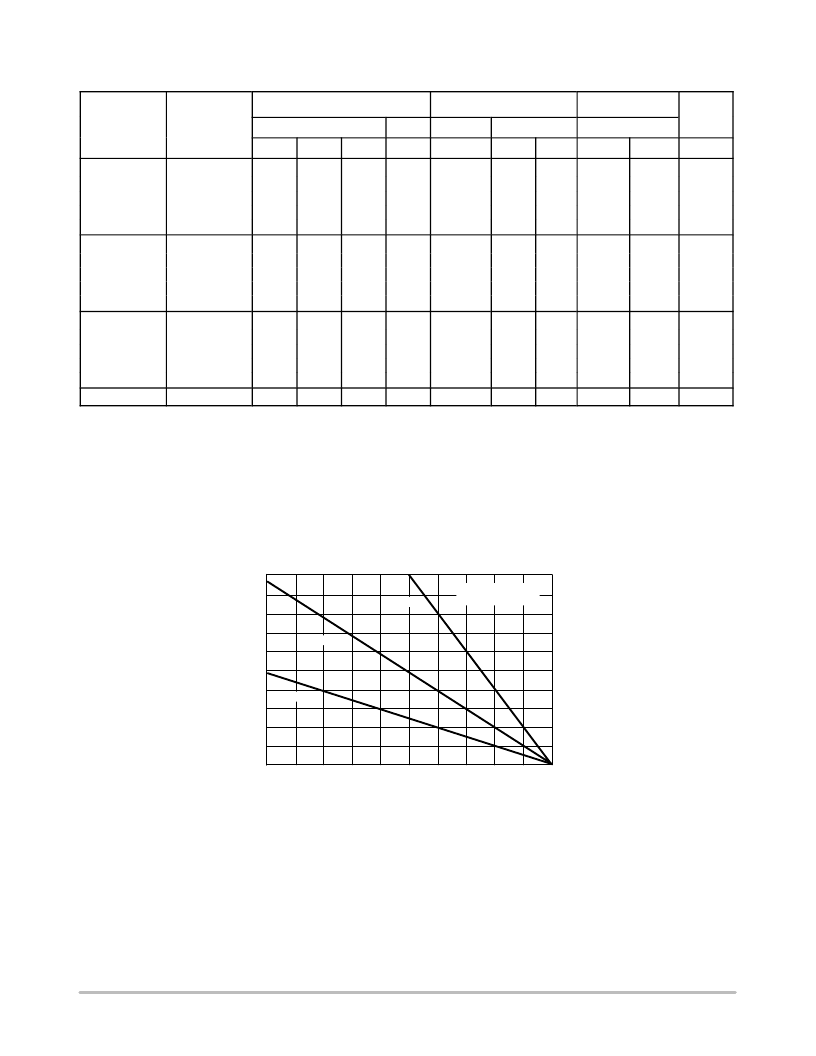
Figure 1. Power Temperature Derating Curve
T
L
, LEAD TEMPERATURE (
°
C)
0
20
40
60
200
80
100
120
140
160
180
0
1
2
3
4
5
L = 1/8
″
L = 3/8
″
L = 1
″
L = LEAD LENGTH
TO HEAT SINK
P
D
,
P
相關PDF資料 |
PDF描述 |
|---|---|
| MZP4734A | 3 Watt DO-41 Surmetic 30 Zener Voltage Regulators |
| MZP4735A | 3 Watt DO-41 Surmetic 30 Zener Voltage Regulators |
| MZP4736A | 3 Watt DO-41 Surmetic 30 Zener Voltage Regulators |
| MZP4737A | 3 Watt DO-41 Surmetic 30 Zener Voltage Regulators |
| MZP4738A | 3 Watt DO-41 Surmetic 30 Zener Voltage Regulators |
相關代理商/技術參數 |
參數描述 |
|---|---|
| MZP4754 | 制造商:MOTOROLA 制造商全稱:Motorola, Inc 功能描述:1.0 WATT SURMETIC 30 SILICON ZENER DIODES |
| MZP4755 | 制造商:MOTOROLA 制造商全稱:Motorola, Inc 功能描述:1.0 WATT SURMETIC 30 SILICON ZENER DIODES |
| MZP4756 | 制造商:MOTOROLA 制造商全稱:Motorola, Inc 功能描述:1.0 WATT SURMETIC 30 SILICON ZENER DIODES |
| MZP4757 | 制造商:MOTOROLA 制造商全稱:Motorola, Inc 功能描述:1.0 WATT SURMETIC 30 SILICON ZENER DIODES |
| MZP4758 | 制造商:MOTOROLA 制造商全稱:Motorola, Inc 功能描述:1.0 WATT SURMETIC 30 SILICON ZENER DIODES |
發布緊急采購,3分鐘左右您將得到回復。