- 您現在的位置:買賣IC網 > PDF目錄361090 > NCP1216D100 (ON SEMICONDUCTOR) PWM Current-Mode Controller for High-Power Universal Off-Line Supplies PDF資料下載
參數資料
| 型號: | NCP1216D100 |
| 廠商: | ON SEMICONDUCTOR |
| 元件分類: | 穩壓器 |
| 英文描述: | PWM Current-Mode Controller for High-Power Universal Off-Line Supplies |
| 中文描述: | 0.005 A SWITCHING CONTROLLER, 110 kHz SWITCHING FREQ-MAX, PDSO8 |
| 封裝: | SOIC-8 |
| 文件頁數: | 13/18頁 |
| 文件大小: | 182K |
| 代理商: | NCP1216D100 |
NCP1216, NCP1216A
http://onsemi.com
13
4. Connect an Auxiliary Winding:
If the mains conditions
are such that you simply can’t match the maximum power
dissipation, then you need to connect an auxiliary winding
to permanently disconnect the startup source.
Overload Operation
In applications where the output current is purposely not
controlled (e.g. wall adapters delivering raw DC level), it is
interesting to implement a true shortcircuit protection. A
shortcircuit actually forces the output voltage to be at a low
level, preventing a bias current to circulate in the
Optocoupler LED. As a result, the FB pin level is pulled up
to 4.2 V, as internally imposed by the IC. The peak current
setpoint goes to the maximum and the supply delivers a
rather high power with all the associated effects. Please note
that this can also happen in case of feedback loss, e.g. a
broken Optocoupler. To account for this situation, NCP1216
hosts a dedicated overload detection circuitry. Once
activated, this circuitry imposes to deliver pulses in a burst
manner with a low dutycycle. The system autorecovers
when the fault condition disappears.
During the startup phase, the peak current is pushed to the
maximum until the output voltage reaches its target and the
feedback loop takes over. This period of time depends on
normal output load conditions and the maximum peak
current allowed by the system. The timeout used by this IC
works with the V
CC
decoupling capacitor: as soon as the
V
CC
decreases from the VCC
OFF
level (typically 12.2 V) the
device internally watches for an overload current situation.
If this condition is still present when the VCC
ON
level is
reached, the controller stops the driving pulses, prevents the
selfsupply current source to restart and puts all the circuitry
in standby, consuming as little as 350 A typical (I
CC3
parameter). As a result, the V
CC
level slowly discharges
toward 0 V. When this level crosses 5.6 V typical, the
controller enters a new startup phase by turning the current
source on: V
CC
rises toward 12.2 V and again delivers
output pulses at the VCC
OFF
crossing point. If the fault
condition has been removed before VCC
ON
approaches,
then the IC continues its normal operation. Otherwise, a new
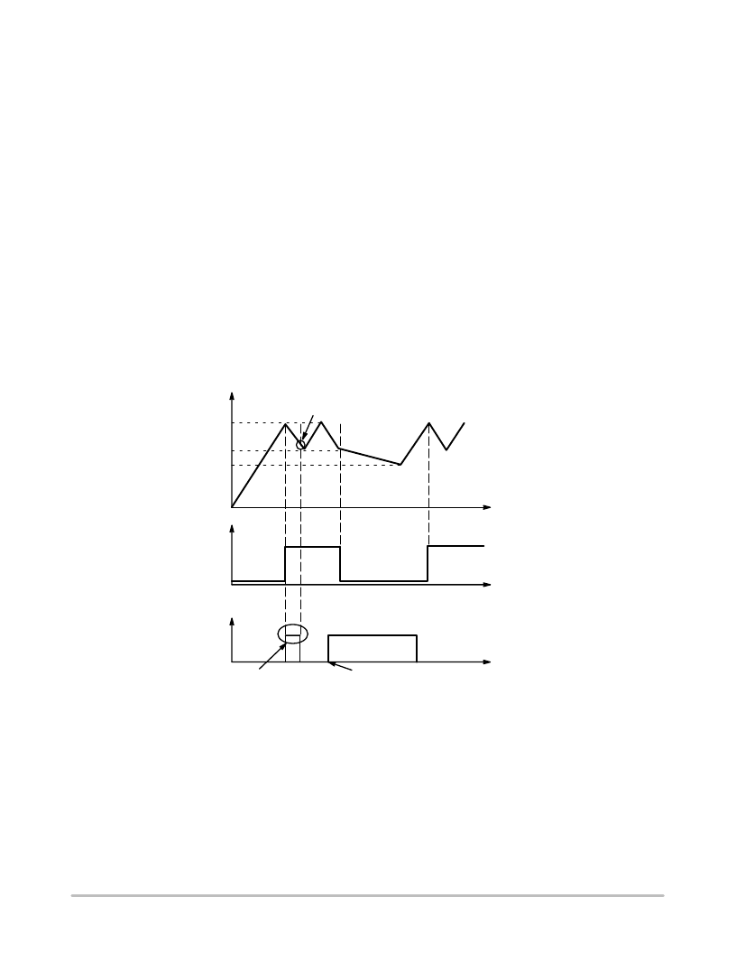
fault cycle takes place. Figure 25 shows the evolution of the
signals in presence of a fault.
Figure 25.
Latchoff
Phase
Time
Time
Time
Fault is
Relaxed
Regulation
Occurs Here
V
CC
12.2 V
10 V
5.6 V
Fault Occurs Here
Startup Phase
Internal
Fault Flag
Driver
Pulses
Drv
Driver
Pulses
VCC
OFF
= 12.2 V
VCC
ON
= 10 V
VCC
latch
= 5.6 V
If the fault is relaxed during the V
CC
natural fall down
sequence, the IC automatically resumes.
If the fault still persists when V
CC
reached VCC
ON
, then the
controller cuts everything off until recovery.
Calculating the VCC Capacitor
As the above section describes, the fall down sequence
depends upon the V
CC
level: how long does it take for the
V
CC
line to go from 12.2 V to 10 V The required time
depends on the startup sequence of your system, i.e. when
you first apply the power to the IC. The corresponding
transient fault duration due to the output capacitor charging
must be less than the time needed to discharge from 12.2 V
to 10 V, otherwise the supply will not properly start. The test
consists in either simulating or measuring in the lab how
much time the system takes to reach the regulation at full
load. Let’s suppose that this time corresponds to 6ms.
Therefore a V
CC
fall time of 10 ms could be well
appropriated in order to not trigger the overload detection
circuitry. If the corresponding IC consumption, including
相關PDF資料 |
PDF描述 |
|---|---|
| NCP1216D133 | PWM Current-Mode Controller for High-Power Universal Off-Line Supplies |
| NCP1216D65 | PWM Current-Mode Controller for High-Power Universal Off-Line Supplies |
| NCP1216D65G | PWM Current-Mode Controller for High-Power Universal Off-Line Supplies |
| NCP1216P100 | PWM Current-Mode Controller for High-Power Universal Off-Line Supplies |
| NCP1216P133 | PWM Current-Mode Controller for High-Power Universal Off-Line Supplies |
相關代理商/技術參數 |
參數描述 |
|---|---|
| NCP1216D100R2 | 功能描述:電流型 PWM 控制器 Current Mode PWM RoHS:否 制造商:Texas Instruments 開關頻率:27 KHz 上升時間: 下降時間: 工作電源電壓:6 V to 15 V 工作電源電流:1.5 mA 輸出端數量:1 最大工作溫度:+ 105 C 安裝風格:SMD/SMT 封裝 / 箱體:TSSOP-14 |
| NCP1216D100R2G | 功能描述:電流型 PWM 控制器 Current Mode PWM RoHS:否 制造商:Texas Instruments 開關頻率:27 KHz 上升時間: 下降時間: 工作電源電壓:6 V to 15 V 工作電源電流:1.5 mA 輸出端數量:1 最大工作溫度:+ 105 C 安裝風格:SMD/SMT 封裝 / 箱體:TSSOP-14 |
| NCP1216D133 | 制造商:ONSEMI 制造商全稱:ON Semiconductor 功能描述:PWM Current-Mode Controller for High-Power Universal Off-Line Supplies |
| NCP1216D133R2 | 功能描述:電流型 PWM 控制器 Current Mode PWM RoHS:否 制造商:Texas Instruments 開關頻率:27 KHz 上升時間: 下降時間: 工作電源電壓:6 V to 15 V 工作電源電流:1.5 mA 輸出端數量:1 最大工作溫度:+ 105 C 安裝風格:SMD/SMT 封裝 / 箱體:TSSOP-14 |
| NCP1216D133R2G | 功能描述:電流型 PWM 控制器 Current Mode PWM RoHS:否 制造商:Texas Instruments 開關頻率:27 KHz 上升時間: 下降時間: 工作電源電壓:6 V to 15 V 工作電源電流:1.5 mA 輸出端數量:1 最大工作溫度:+ 105 C 安裝風格:SMD/SMT 封裝 / 箱體:TSSOP-14 |
發布緊急采購,3分鐘左右您將得到回復。