- 您現在的位置:買賣IC網 > Datasheet目錄46 > NSI45090DDT4G (ON Semiconductor)IC LED DRIVER/REG CCR TP-FA Datasheet資料下載
參數資料
| 型號: | NSI45090DDT4G |
| 廠商: | ON Semiconductor |
| 文件頁數: | 5/6頁 |
| 文件大小: | 138K |
| 描述: | IC LED DRIVER/REG CCR TP-FA |
| 產品變化通告: | Product Obsolescence 08/Apr/2011 |
| 標準包裝: | 1 |
| 功能: | * |
| 檢測方法: | * |
| 精確度: | * |
| 輸入電壓: | * |
| 電流 - 輸出: | * |
| 工作溫度: | * |
| 安裝類型: | 表面貼裝 |
| 封裝/外殼: | TO-252-3,DPak(2 引線+接片),SC-63 |
| 供應商設備封裝: | DPAK-3 |
| 包裝: | 標準包裝 |
| 其它名稱: | NSI45090DDT4GOSDKR |
NSI45090DDT4G
http://onsemi.com
5
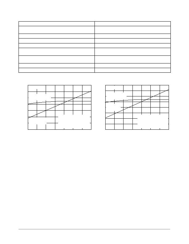
Comparison of LED Circuit using CCR vs. Resistor Biasing
ON Semiconductor CCR Design
Resistor Biased Design
Constant brightness over full Supply Voltage
(more efficient), see Figure 10
Large variations in brightness over full Automotive Supply Voltage
Little variation of power in LEDs, see Figure 11
Large variations of current (power) in LEDs
Constant current extends LED strings lifetime, see Figure 10
High Supply Voltage/ Higher Current in LED strings limits lifetime
Current decreases as voltage increases, see Figure 10
Current increases as voltage increases
Current supplied to LED string decreases as temperature
increases (self-limiting), see Figure 2
LED current decreases as temperature increases
Single resistor is used for current select
Requires costly inventory
(need for several resistor values to match LED intensity)
Fewer components, less board space required
More components, more board space required
Surface mount component
Through-hole components
Figure 10. Series Circuit Current
Figure 11. LED Power
V
in
(V)
V
in
(V)
16
15
14
13
12
11
10
9
40
60
80
120
0
20
15
16
14
13
12
11
10
9
100
200
300
400
T
A
= 25癈
Circuit Current with
CCR Device
Circuit Current
with 83.3 W
Representative Test Data
for Figure 8 Circuit, Current
of LEDs, FR4 @ 300 mm
2
,
2 oz Copper Area
500
T
A
= 25癈
LED Power with
CCR Device
LED Power
with 83.3 W
Representative Test Data
for Figure 8 Circuit, Pd of
LEDs, FR4 @ 300 mm
2
,
2 oz Copper Area
0
600
700
100
800
140
Current Regulation: Pulse Mode (I
reg(P)
) vs DC
Steady-State (I
reg(SS)
)
There are two methods to measure current regulation:
Pulse mode (I
reg(P)
) testing is applicable for factory and
incoming inspection of a CCR where test times are a
minimum. (t <
300 ms). DC Steady-State (I
reg(SS)
) testing
is applicable for application verification where the CCR will
be operational for seconds, minutes, or even hours. ON
Semiconductor has correlated the difference in I
reg(P)
to
I
reg(SS)
for stated board material, size, copper area and
copper thickness. I
reg(P)
will always be greater than I
reg(SS)
due to the die temperature rising during I
reg(SS)
. This heating
effect can be minimized during circuit design with the
correct selection of board material, metal trace size and
weight, for the operating current, voltage, board operating
temperature (T
A
) and package. (Refer to Thermal
Characteristics table).
相關PDF資料 |
PDF描述 |
|---|---|
| NSI45090JDT4G | 90MA ADJUSTABLE CURRENT REG DPAK |
| NSI50350ADT4G | IC REG/LED DRIVER 350MA DPAK |
| NSI50350AST3G | IC REG/LED DRIVER 350MA SMC |
| NVT210DMTR2G | IC TEMP SENSOR DGTL 8-WDFN |
| PI5L102LE | IC HOT SWAP PULL-UP SW 20-TSSOP |
相關代理商/技術參數 |
參數描述 |
|---|---|
| NSI45090JD | 制造商:ONSEMI 制造商全稱:ON Semiconductor 功能描述:Adjustable Constant Current Regulator & LED Driver |
| NSI45090JDT4G | 功能描述:LED照明驅動器 RoHS:否 制造商:STMicroelectronics 輸入電壓:11.5 V to 23 V 工作頻率: 最大電源電流:1.7 mA 輸出電流: 最大工作溫度: 安裝風格:SMD/SMT 封裝 / 箱體:SO-16N |
| NSI50010YT1G | 功能描述:LED照明驅動器 50 V 10 mA +/- 30% 460 mW package RoHS:否 制造商:STMicroelectronics 輸入電壓:11.5 V to 23 V 工作頻率: 最大電源電流:1.7 mA 輸出電流: 最大工作溫度: 安裝風格:SMD/SMT 封裝 / 箱體:SO-16N |
| NSI50010YT1G | 制造商:ON Semiconductor 功能描述:Constant Current Regulator & LED Driver |
| NSI50010YT1G/H | 制造商:ON Semiconductor 功能描述: |
發布緊急采購,3分鐘左右您將得到回復。