- 您現在的位置:買賣IC網 > PDF目錄382362 > NSL-32 (Silonex Inc.) Optocoupler PDF資料下載
參數資料
| 型號: | NSL-32 |
| 廠商: | Silonex Inc. |
| 英文描述: | Optocoupler |
| 中文描述: | 光耦 |
| 文件頁數: | 1/1頁 |
| 文件大小: | 41K |
| 代理商: | NSL-32 |
5200 St. Patrick St., Montreal
Que., H4E 4N9, Canada
Tel: 514-768-8000
Fax: 514-768-8889
The Old Railway, Princes Street
Ulverston, Cumbria, LA12 7NQ, UK
Tel: 01 229 581 551
Fax: 01 229 581 554
QF-84
NSL-32
Optocoupler
Features
Compact, moisture resistant package
Low LED current
Passive resistance output
Description
This optocoupler consists of an LED input optically
coupled to a photocell. The photocell resistance is
high when the LED current is “off” and low resistance
when the LED current is “on”.
Absolute Maximum Ratings
Storage Temperature
Operating Temperature
Soldering Temperature (1)
Isolation Voltage (peak)
-40 to +75
°
C
-40 to +75
°
C
260
°
C
2000V
Note:
(1) >2 mm from case for <5 sec.
(2) Derate linearly to 0 at 75
°
C
(3) The Rise Time, T
R
, is the time required for
the dark to light change in conductance to
reach 63% of its final value.
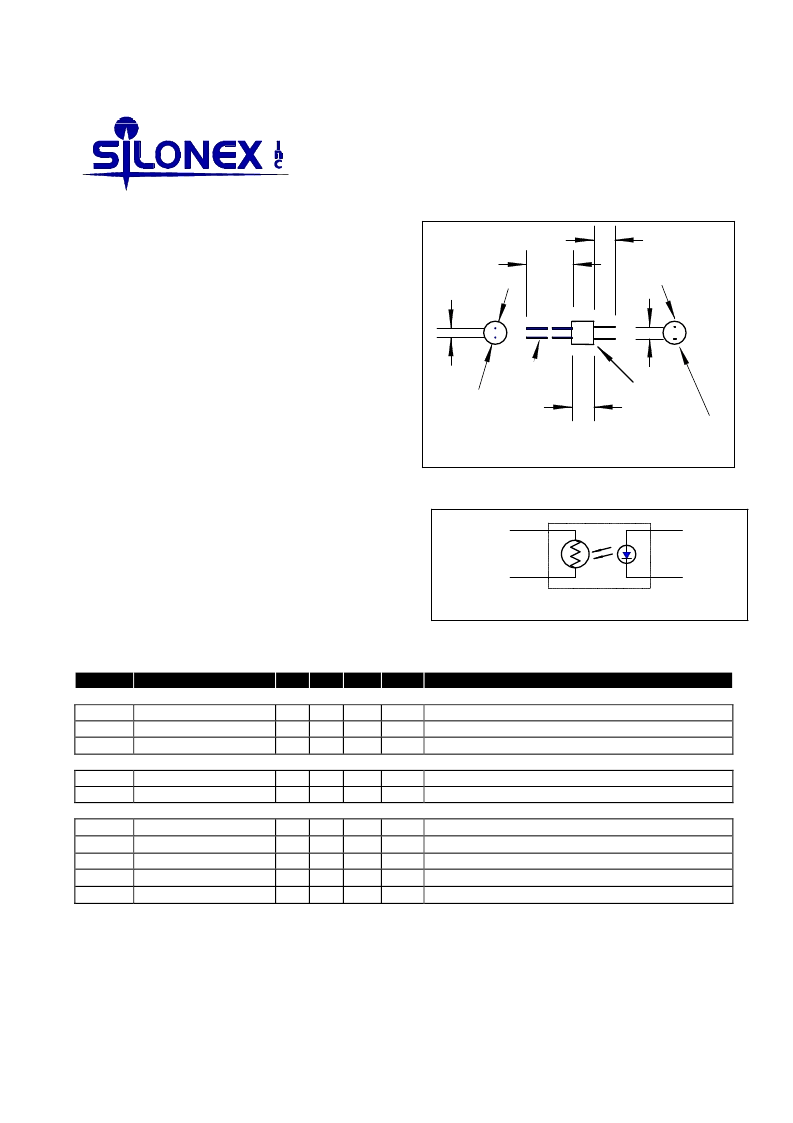
Photocell
LED
-
Color dot
5.72 - 6.22
0.45-0.56
cell leads
Dimensions in mm.
Lead spacing tolerance: +/-0.13
Anode lead
0.25 x 0.51
Cathode lead
0.25 x 0.64
6.0 - 6.5
+
25.4 min.
5.7 min.
2.54
3.30
+
-
LED
Photocell
Circuit Schematic
Electrical Characteristics
(T
A
=25
°
C unless otherwise noted)
Symbol Parameter
LED
I
F
Forward Current
V
F
Forward Voltage
I
R
Reverse Current
Cell
V
C
Maximum Cell Voltage
P
D
Power Dissipation
Coupled
R
ON
On Resistance
R
OFF
Off Resistance
T
R
Rise Time
T
F
Decay Time
Cell Temp Coefficient
Specifications subject to change without notice
Min. Typ. Max. Units Test Conditions
40
2.0
100
mA
V
μ
A
(2)
I
F
= 16 mA
V
R
= 4V
60
50
V
(Peak AC or DC)
mW (2)
500
K
msec Time to 63% of final conductance @ I
F
= 16mA (3)
msec Time to 100K
after removal of I
F
= 16mA
%/
°
C I
F
> 5 mA
I
F
= 20 mA
10 sec after I
F
= 0, 5Vdc on cell.
500
3.5
500
1.0
103708 REV 1
相關PDF資料 |
PDF描述 |
|---|---|
| NSL-3510 | TO-5 Photocells Hermetic Package |
| NSL-3520 | TO-5 Photocells Hermetic Package |
| NSL-3530 | TO-5 Photocells Hermetic Package |
| NSL-3540 | TO-5 Photocells Hermetic Package |
| NSL-4510 | TO-5 Photocells Hermetic Package |
相關代理商/技術參數 |
參數描述 |
|---|---|
| NSL-32AA | 制造商:ADVANCED PHOTONIX 功能描述:ELECTRONIC PART |
| NSL-32B-100 | 制造商:未知廠家 制造商全稱:未知廠家 功能描述:OOPTOCOUPLERS |
| NSL32B-103 | 制造商:Advanced Photonix Inc 功能描述:Optoelectronics,Optocoupler, R(on) 0.90ohms,R(off) 500Kohms, V(f),2.0V, I(f), 40mA, |
| NSL-32H-100 | 制造商:SILONEX 制造商全稱:SILONEX 功能描述:OPTOCOUPLERS |
| NSL-32H-101 | 制造商:SILONEX 制造商全稱:SILONEX 功能描述:OPTOCOUPLERS |
發布緊急采購,3分鐘左右您將得到回復。