- 您現在的位置:買賣IC網 > PDF目錄382365 > P2065A-08TT MCU CMOS 18LD 20MHz LOW PWR, -40C to +85C, 18-SOIC 300mil, TUBE PDF資料下載
參數資料
| 型號: | P2065A-08TT |
| 英文描述: | MCU CMOS 18LD 20MHz LOW PWR, -40C to +85C, 18-SOIC 300mil, TUBE |
| 中文描述: | 外圍芯片 |
| 文件頁數: | 3/7頁 |
| 文件大小: | 94K |
| 代理商: | P2065A-08TT |
Final Product Specification
P2065
Jan., 2001
Revision D
3160 De La Cruz Blvd., Suite 200 Santa Clara CA 95054 Tel (408)
Fax (408) 748-000
9
SPREAD SPECTRUM SELECTION
Table 1 illustrates the possible spread spectrum options. The optimal setting should minimize system
EMI to the fullest without affecting system performance. The spreading is described as a percentage
deviation of the center frequency (Note: the center frequency is the frequency of the external reference
input on CLKIN, Pin 1).
Example
: P2065 is designed for high resolution flat panel applications and is able to support XGA (1024
X 768) flat panel that operates on 65MHz (Fin) clock speed. A spreading selection of SR1=0, SR0=1 and
modulation rate selection MRA=1 provides a percentage deviation of +/-1.00% (see Table 1) of Fin. This
results in frequency on ModOUT being swept from 64.35 MHz to 65.65 MHz at a modulation rate of
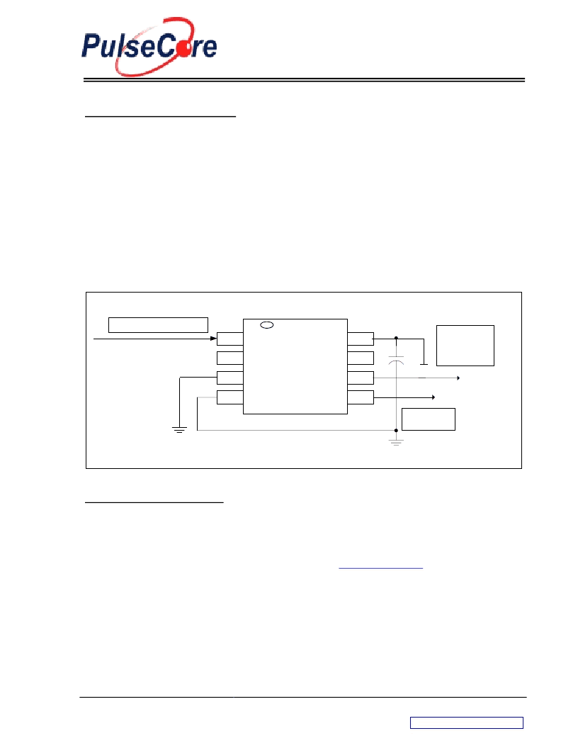
33.85KHz (see Table 1). This particular example (see Figure 3) given here is a common EMI reduction
method for notebook LCD panel and has already been implemented by most of the leading OEM and
mobile graphic accelerator manufacturers.
Figure 3 – P2065 Application Schematic For Mobile LCD Graphics Controllers
P2065
This signal is
connected back to the
Spread Spectrum Input
Pin (SSIN) of the
Graphics Accelerator.
VDD
1
8
6
4
3
2
7
5
CLKIN
MRA
SR1
VSS
VDD
SSON
ModOUT
SR0
0.1uF
65 MHZ From Graphics Accelerator
Digital Control for SS
enable or disable
EMC SOFTWARE SIMULATION
By using PulseCore Semiconductor, Inc.’s proprietary EMC simulation software –
EMI-lator
, radiated
system level EMI analysis can be made easier to allow a quantitative assessment on PulseCore’s EMI
reduction products. The simulation engine of this EMC software has already been characterized to
correlate with the electrical characteristics of PulseCore EMI reduction IC’s.
Figure 4
below is an
example of the simulation result. Please visit our web site at
www.pulsecore.com
for information on how
to obtain a free copy and demonstration of
EMI-lator
.
相關PDF資料 |
PDF描述 |
|---|---|
| P21010-07 | x1 Fast Page Mode DRAM |
| P21010-08 | x1 Fast Page Mode DRAM |
| P21010-10 | x1 Fast Page Mode DRAM |
| P21010-12 | x1 Fast Page Mode DRAM |
| Z21010-07 | x1 Fast Page Mode DRAM |
相關代理商/技術參數 |
參數描述 |
|---|---|
| P2067 | 制造商:未知廠家 制造商全稱:未知廠家 功能描述:NPN-OUTPUT AC-INPUT OPTOCOUPLER |
| P2068 | 功能描述:罩類、盒類及殼類產品 18.44 x 14.44 Panel NEMA 4X Steel RoHS:否 制造商:Bud Industries 產品:Boxes 外部深度:6.35 mm 外部寬度:6.35 mm 外部高度:2.56 mm NEMA 額定值: IP 等級: 材料:Acrylonitrile Butadiene Styrene (ABS) 顏色:Red |
| P-206942 | 制造商:Amphenol Corporation 功能描述:MIL-C-26500 CONNS - ENV CONNS FOR MIL/AEROSPACE APPLICATIONS - Bulk |
| P-206943 | 制造商:Amphenol Corporation 功能描述:MIL-C-26500 - Bulk |
| P-207362-11 | 制造商:Amphenol Corporation 功能描述:HERMETICS-ALL SERIES - Bulk |
發布緊急采購,3分鐘左右您將得到回復。