- 您現在的位置:買賣IC網 > PDF目錄382369 > P8C15416Y-12 IC-8-BIT CMOS CPU PDF資料下載
參數資料
| 型號: | P8C15416Y-12 |
| 英文描述: | IC-8-BIT CMOS CPU |
| 中文描述: | 集成電路8位CMOS處理器 |
| 文件頁數: | 6/25頁 |
| 文件大小: | 154K |
| 代理商: | P8C15416Y-12 |
80C32/80C52
6
Rev. I
–
September 18, 1998
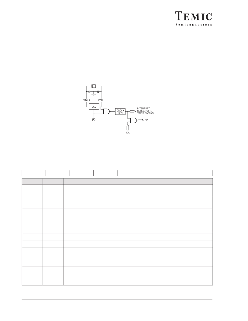
6. Idle And Power Down Operation
Figure 3. shows the internal Idle and Power Down clock configuration. As illustrated, Power Down operation stops
the oscillator. Idle mode operation allows the interrupt, serial port, and timer blocks to continue to function, while the
clock to the CPU is gated off.
These special modes are activated by software via the Special Function Register, PCON. Its hardware address is 87H.
PCON is not bit addressable.
Figure 3. Idle and Power Down Hardware
PCON: Power Control Register
(MSB)
7
(LSB)
0
6
5
4
3
2
1
SMOD
–
–
–
GF1
GF0
PD
IDL
Symbol
Position
Name and Function
SMOD
PCON.7
Double Baud rate bit
When set to a 1, the baud rate is doubled when the serial port is being used in either modes 1, 2 or 3.
–
PCON.6
Reserved
The value read from this bit is indeterminate. Do not set this bit.
–
PCON.5
Reserved
The value read from this bit is indeterminate. Do not set this bit.
–
PCON.4
Reserved
The value read from this bit is indeterminate. Do not set this bit.
GF1
PCON.3
General–purpose flag bit
GF0
PCON.2
General–purpose flag bit
PD
(1)
PCON.1
Power Down bit. Setting this bit activates power down operation
Cleared by hardware when an interrupt or reset occurs.
Set to activate the Power–Down mode.
If IDL and PD are both set, PD takes precedence.
IDL
(1)
PCON.0
Idle mode bit
Cleared by hardware when an interrupt or reset occurs.
Set to activate the Idle mode.
If IDL and PD are both set, PD takes precedence.
1.
If 1’s are written to PD and IDL at the same time. PD takes, precedence. The reset value of PCON is (000X0000).
相關PDF資料 |
PDF描述 |
|---|---|
| P903 | |
| P90C101ABA | 16-Bit Microcontroller |
| P90C101ABB | 16-Bit Microcontroller |
| P90CL301 | Low voltage 16-bit microcontroller |
| P90CL301BFH | Low voltage 16-bit microcontroller |
相關代理商/技術參數 |
參數描述 |
|---|---|
| P8-CG-16 | 制造商:ITT Interconnect Solutions 功能描述:P8-CG-16 - Bulk |
| P8D | 制造商:PREMO 制造商全稱:PREMO CORPORATION S.L 功能描述:Coils and Chokes for general use |
| P8D-100K | 制造商:PREMO 制造商全稱:PREMO CORPORATION S.L 功能描述:Coils and Chokes for general use |
| P8D-101K | 制造商:PREMO 制造商全稱:PREMO CORPORATION S.L 功能描述:Coils and Chokes for general use |
| P8D-102K | 制造商:PREMO 制造商全稱:PREMO CORPORATION S.L 功能描述:Coils and Chokes for general use |
發布緊急采購,3分鐘左右您將得到回復。