- 您現在的位置:買賣IC網 > PDF目錄382370 > PA13 Operational Amplifier PDF資料下載
參數資料
| 型號: | PA13 |
| 英文描述: | Operational Amplifier |
| 中文描述: | 運算放大器 |
| 文件頁數: | 4/4頁 |
| 文件大小: | 69K |
| 代理商: | PA13 |
APEX MICROTECHNOLOGY CORPORATION
5980 NORTH SHANNON ROAD
TUCSON, ARIZONA 85741
USA
APPLICATIONS HOTLINE: 1 (800) 546-2739
PA13U REV. F FEBRUARY 2001 2001 Apex Microtechnology Corp.
SHORT TO
±
V
C, L, OR EMF LOAD
.43A
.65A
1.0A
1.7A
2.7A
3.4A
4.5A
SHORT TO
COMMON
3.0A
3.4A
3.9A
4.5A
5.4A
6.7A
9.0A
±
V
S
45V
40V
35V
30V
25V
20V
15V
These simplified limits may be exceeded with further analysis using the operat-
ing conditions for a specific application.
CURRENT LIMITING
Refer to Application Note 9, "Current Limiting", for details of both
fixed and foldover current limit operation. Visit the Apex web site
at www.apexmicrotech.com for a copy of Power_design.exe which
plots current limits vs. steady state SOA. Beware that current limit
should be thought of as a +/
–
20% function initially and varies about
2:1 over the range of
–
55
°
C to 125
°
C.
For fixed current limit, leave pin 4 open and use equations 1 and 2.
R
CL
= 0.65/L
CL
I
CL
= 0.65/R
CL
Where:
I
CL
is the current limit in amperes.
R
CL
is the current limit resistor in ohms.
For certain applications, foldover current limit adds a slope to
the current limit which allows more power to be delivered to the
load without violating the SOA. For maximum foldover slope,
ground pin 4 and use equations 3 and 4.
(1)
(2)
0.65 + (Vo * 0.014)
I
CL
=
(3)
R
CL
0.65 + (Vo * 0.014)
R
CL
=
(4)
I
CL
Where:
Vo is the output voltage in volts.
Most designers start with either equation 1 to set R
CL
for the
desired current at 0v out, or with equation 4 to set R
at the
maximum output voltage. Equation 3 should then be used to plot
the resulting foldover limits on the SOA graph. If equation 3 results
in a negative current limit, foldover slope must be reduced. This
can happen when the output voltage is the opposite polarity of the
supply conducting the current.
In applications where a reduced foldover slope is desired, this
can be achieved by adding a resistor (R
) between pin 4 and
ground. Use equations 4 and 5 with this new resistor in the circuit.
0.65 +10.14 + R
FO
I
CL
=
(5)
R
CL
0.65 +10.14 + R
FO
R
CL
=
(6)
I
CL
Where:
R
FO
is in K ohms.
OPERATING
CONSIDERATIONS
PA13
GENERAL
Please read Application Note 1 "General Operating Consider-
ations" which covers stability, supplies, heat sinking, mounting,
current limit, SOA interpretation, and specification interpretation.
Visit www.apexmicrotech.com for design tools that help automate
tasks such as calculations for stability, internal power dissipation,
current limit; heat sink selection; Apex
’
s complete Application
Notes library; Technical Seminar Workbook; and Evaluation Kits.
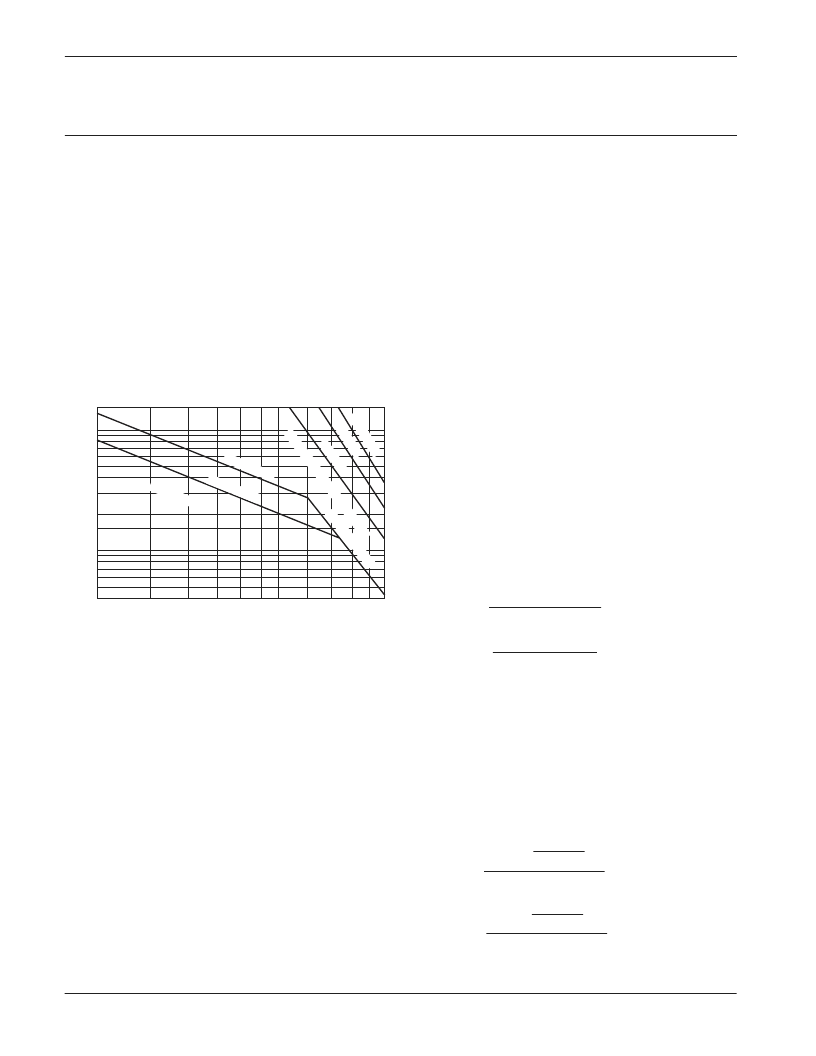
SAFE OPERATING AREA (SOA)
The output stage of most power amplifiers has three distinct
limitations:
1. The current handling capability of the transistor geometry and
the wire bonds.
2. The second breakdown effect which occurs whenever the
simultaneous collector current and collector-emitter voltage
exceeds specified limits.
3. The junction temperature of the output transistors.
The SOA curves combine the effect of all limits for this Power Op
Amp. For a given application, the direction and magnitude of the
output current should be calculated or measured and checked
against the SOA curves. This is simple for resistive loads but more
complex for reactive and EMF generating loads. However, the
following guidelines may save extensive analytical efforts.
1. Capacitive and dynamic* inductive loads up to the following
maximum are safe with the current limits set as specified.
CAPACITIVE LOAD
I
LIM
= 5A
200
μ
F
500
μ
F
2.0mF
7.0mF
25mF
60mF
150mF
INDUCTIVE LOAD
I
LIM
= 5A
5mH
15mH
50mH
150mH
500mH
1,000mH
2,500mH
±
V
S
50V
40V
35V
30V
25V
20V
15V
I
LIM
= 10A
125
μ
F
350
μ
F
850
μ
F
2.5mF
10mF
20mF
60mF
I
LIM
= 10A
2.0mH
3.0mH
5.0mH
10mH
20mH
30mH
50mH
*If the inductive load is driven near steady state conditions, allowing the output
voltage to drop more than 12.5V below the supply rail with I
= 10A or 27V below
the supply rail with I
= 5A while the amplifier is current limiting, the inductor
must be capacitively coupled or the current limit must be lowered to meet SOA
criteria.
2. The amplifier can handle any EMF generating or reactive load
and short circuits to the supply rail or common if the current
limits are set as follows at T
C
= 25
°
C:
t1m
SECONDBREAKDOWN
Tc=25°C
Tc=85°C
THERMAL
sed tt
10
15
20
25
30 35 40
50
60 70 80 90
15
10
8
6
4
3
2
1.5
1
.8
.6
.4
SUPPLY TO OUTPUT DIFFERENTIAL VOLTAGE V
–
V (V)
O
–
V
相關PDF資料 |
PDF描述 |
|---|---|
| PA13A | Operational Amplifier |
| PA18 | Voltage-Feedback Operational Amplifier |
| PA18A | Voltage-Feedback Operational Amplifier |
| PA19 | Voltage-Feedback Operational Amplifier |
| PA19A | Voltage-Feedback Operational Amplifier |
相關代理商/技術參數 |
參數描述 |
|---|---|
| PA-13 | 制造商:Electro Switch Corp 功能描述: 制造商:ELECTROSWITCH 功能描述: |
| PA13_09 | 制造商:CIRRUS 制造商全稱:Cirrus Logic 功能描述:Power Operational Amplifier |
| PA13_10 | 制造商:CIRRUS 制造商全稱:Cirrus Logic 功能描述:Power Operational Amplifier |
| PA1300.9 | 功能描述:HANDLE CRIMP REPLACEMNT 1300 SER RoHS:是 類別:工具 >> 壓接器,施用器,壓力機 - 配件 系列:1300 標準包裝:1 系列:- 其它名稱:512A512A-NDQ1137690B |
| PA-1300-03/04 | 制造商:Lite-On Semiconductor Corporation 功能描述:PA-1300-03/04 - Bulk |
發布緊急采購,3分鐘左右您將得到回復。