- 您現在的位置:買賣IC網 > PDF目錄382383 > PCM1710U Stereo Audio DIGITAL-TO-ANALOG CONVERTER PDF資料下載
參數資料
| 型號: | PCM1710U |
| 英文描述: | Stereo Audio DIGITAL-TO-ANALOG CONVERTER |
| 中文描述: | 立體聲音頻數字模擬轉換器 |
| 文件頁數: | 10/17頁 |
| 文件大小: | 192K |
| 代理商: | PCM1710U |
PCM1710U
10
FUNCTIONAL DESCRIPTION
PCM1710 has several built-in functions including digital
attenuation, digital de-emphasis and soft mute. These func-
tions are software controlled. PCM1710 can be operated in
two different modes,
Serial
or
Parallel
. Serial Mode is a
three-wire interface using pin 26 (MD), pin 27 (MC), and pin
28 (ML). Data on these pins are used to control de-emphasis
mode, mute, double-speed dubbing, input resolution and
input format. PCM1710 can also be operated in parallel
mode, where static control signals are used on pin 26 (DM1),
pin 27 (DM2), and pin 28 (DSD). Operation of both of these
modes are covered in detail in the next sections.
CAUTION
: Mode control signals operate on level triggered
logic. The minimum timing conditions detailed in Figures 5
and 6 MUST be observed.
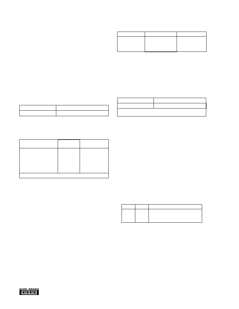
DM1 (Pin 26)
DM2 (Pin 27)
De-emphasis
L
H
L
H
L
L
H
H
OFF
32kHz
48kHz
44.1kHz
PARALLEL-MODE: DE-EMPHASIS CONTROL
(PIN 24 [MODE] = L)
TABLE V. De-emphasis (Pins 26 and 27).
In the parallel mode, de-emphasis conditions are controlled
by the logic levels on pin 26 (DM1) and pin 27 (DM2). For
PCM1710, de-emphasis can operate at 32kHz, 44.1kHz,
48kHz, or disabled.
MODE CONTROL: SERIAL/PARALLEL SELECTION
MODE = H
Serial Mode
MODE = L
Parallel Mode
TABLE III. Serial and Parallel Mode are Selectable by
MODE Pin (Pin 24).
MODE CONTROL: SELECTABLE FUNCTIONS
TABLE IV. Selectable Functions in Serial Mode and
Parallel Mode.
SERIAL MODE
(MODE = H)
PARALLEL MODE
(MODE = L)
FUNCTION
Input Data Format Selection
Input Data Bit Selection
Input LRCI Polarity Selection
De-emphasis Control
Mute
Attenuation
Double Speed Dubbing
0
0
0
0
0
0
0
X(Normal Mode Fixed)
X(16-bit Fixed)
X
0
0
X
0
NOTE: 0: Selectable, X: Not Selectable.
Table IV indicates which functions are selectable within the
user’s chosen mode. All of the functions shown are select-
able within the serial mode, but only de-emphasis control,
mute and double-speed dubbing may be selected when using
PCM1710 in the parallel mode.
PARALLEL-MODE: DOUBLE-SPEED DUBBING
CONTROL (PIN 24 [MODE] = L)
DSD = H
Normal Mode
DSD = L
Double-Speed Dubbing Mode
NOTE: When the Double-Speed Dubbing Mode is selected, the System
Clock must be 384fs (CKSL: Pin 23 = H).
TABLE VI. DSD (Pin 28).
In the parallel mode, double-speed dubbing can be enabled
by holding pin 28 (DSD) at a logic “low”.
CAUTION:
Double-speed dubbing cannot operate if the
system clock is set at 256fs.
SERIAL MODE CONTROL
In order to use all of PCM1710’s functionality, the
serial
mode control
should be used. PCM1710 must be addressed
three separate times to set all of the various registers and
flags that control these functions.
Table VII together with Figure 6 details the control of the
PCM1710 in the serial mode. Internal latches are used to
hold this serial data until the PCM1710 is enabled to use the
data. The serial mode is used by applying clocked data to the
following pins:
NAME
PIN
FUNCTION
MC
ML
MD
27
28
26
Clock for Strobing in Data
Latches Data into the Registers
8-bit Data Word Defining Operation
相關PDF資料 |
PDF描述 |
|---|---|
| PCM1712 | DIGITAL-TO-ANALOG CONVERTER |
| PCM1712U | DIGITAL-TO-ANALOG CONVERTER |
| PCM1715 | Dual Voltage Output CMOS Delta-Sigma DIGITAL-TO-ANALOG CONVERTER With On-Chip Digital Filter |
| PCM1715U | Dual Voltage Output CMOS Delta-Sigma DIGITAL-TO-ANALOG CONVERTER With On-Chip Digital Filter |
| PCM1716 | 24-Bit, 96kHz Sampling CMOS Delta-Sigma Stereo Audio DIGITAL-TO-ANALOG CONVERTER |
相關代理商/技術參數 |
參數描述 |
|---|---|
| PCM1710U | 制造商:BURR-BROWN 功能描述:IC DAC AUDIO SMD 1710 SOIC28 制造商:Texas Instruments 功能描述:Digital-Analog Converter IC Interface Ty |
| PCM1710U/1K | 功能描述:數模轉換器- DAC Dual Voltage Output CMOS D-S DAC RoHS:否 制造商:Texas Instruments 轉換器數量:1 DAC 輸出端數量:1 轉換速率:2 MSPs 分辨率:16 bit 接口類型:QSPI, SPI, Serial (3-Wire, Microwire) 穩定時間:1 us 最大工作溫度:+ 85 C 安裝風格:SMD/SMT 封裝 / 箱體:SOIC-14 封裝:Tube |
| PCM1710U/1KG4 | 功能描述:數模轉換器- DAC Dual Voltage Output CMOS D-S DAC RoHS:否 制造商:Texas Instruments 轉換器數量:1 DAC 輸出端數量:1 轉換速率:2 MSPs 分辨率:16 bit 接口類型:QSPI, SPI, Serial (3-Wire, Microwire) 穩定時間:1 us 最大工作溫度:+ 85 C 安裝風格:SMD/SMT 封裝 / 箱體:SOIC-14 封裝:Tube |
| PCM1710UG4 | 功能描述:數模轉換器- DAC Dual Voltage Output CMOS D-S DAC RoHS:否 制造商:Texas Instruments 轉換器數量:1 DAC 輸出端數量:1 轉換速率:2 MSPs 分辨率:16 bit 接口類型:QSPI, SPI, Serial (3-Wire, Microwire) 穩定時間:1 us 最大工作溫度:+ 85 C 安裝風格:SMD/SMT 封裝 / 箱體:SOIC-14 封裝:Tube |
| PCM1712 | 制造商:BB 制造商全稱:BB 功能描述:DIGITAL-TO-ANALOG CONVERTER |
發布緊急采購,3分鐘左右您將得到回復。