- 您現(xiàn)在的位置:買賣IC網(wǎng) > PDF目錄376275 > PSD913490MT (意法半導(dǎo)體) Flash In-System Programmable ISP Peripherals For 8-bit MCUs PDF資料下載
參數(shù)資料
| 型號(hào): | PSD913490MT |
| 廠商: | 意法半導(dǎo)體 |
| 英文描述: | Flash In-System Programmable ISP Peripherals For 8-bit MCUs |
| 中文描述: | Flash在系統(tǒng)可編程ISP的外設(shè)的8位微控制器 |
| 文件頁(yè)數(shù): | 64/110頁(yè) |
| 文件大小: | 1737K |
| 代理商: | PSD913490MT |
第1頁(yè)第2頁(yè)第3頁(yè)第4頁(yè)第5頁(yè)第6頁(yè)第7頁(yè)第8頁(yè)第9頁(yè)第10頁(yè)第11頁(yè)第12頁(yè)第13頁(yè)第14頁(yè)第15頁(yè)第16頁(yè)第17頁(yè)第18頁(yè)第19頁(yè)第20頁(yè)第21頁(yè)第22頁(yè)第23頁(yè)第24頁(yè)第25頁(yè)第26頁(yè)第27頁(yè)第28頁(yè)第29頁(yè)第30頁(yè)第31頁(yè)第32頁(yè)第33頁(yè)第34頁(yè)第35頁(yè)第36頁(yè)第37頁(yè)第38頁(yè)第39頁(yè)第40頁(yè)第41頁(yè)第42頁(yè)第43頁(yè)第44頁(yè)第45頁(yè)第46頁(yè)第47頁(yè)第48頁(yè)第49頁(yè)第50頁(yè)第51頁(yè)第52頁(yè)第53頁(yè)第54頁(yè)第55頁(yè)第56頁(yè)第57頁(yè)第58頁(yè)第59頁(yè)第60頁(yè)第61頁(yè)第62頁(yè)第63頁(yè)當(dāng)前第64頁(yè)第65頁(yè)第66頁(yè)第67頁(yè)第68頁(yè)第69頁(yè)第70頁(yè)第71頁(yè)第72頁(yè)第73頁(yè)第74頁(yè)第75頁(yè)第76頁(yè)第77頁(yè)第78頁(yè)第79頁(yè)第80頁(yè)第81頁(yè)第82頁(yè)第83頁(yè)第84頁(yè)第85頁(yè)第86頁(yè)第87頁(yè)第88頁(yè)第89頁(yè)第90頁(yè)第91頁(yè)第92頁(yè)第93頁(yè)第94頁(yè)第95頁(yè)第96頁(yè)第97頁(yè)第98頁(yè)第99頁(yè)第100頁(yè)第101頁(yè)第102頁(yè)第103頁(yè)第104頁(yè)第105頁(yè)第106頁(yè)第107頁(yè)第108頁(yè)第109頁(yè)第110頁(yè)
PSD813F2, PSD833F2, PSD834F2, PSD853F2, PSD854F2
64/110
For Users of the HC11 (or compatible)
The HC11 turns off its E clock when it sleeps.
Therefore, if you are using an HC11 (or compati-
ble) in your design, and you wish to use the Pow-
er-down mode, you must not connect the E clock
to CLKIN (PD1). You should instead connect a
crystal oscillator to CLKIN (PD1). The crystal oscil-
lator frequency must be
less than
15 times the fre-
quency of AS. The reason for this is that if the
frequency is greater than 15 times the frequency
of AS, the PSD keeps going into Power-down
mode.
Other Power Saving Options
The PSD offers other reduced power saving op-
tions that are independent of the Power-down
mode. Except for the SRAM Stand-by and PSD
Chip Select Input (CSI, PD2) features, they are en-
abled by setting bits in PMMR0 and PMMR2.
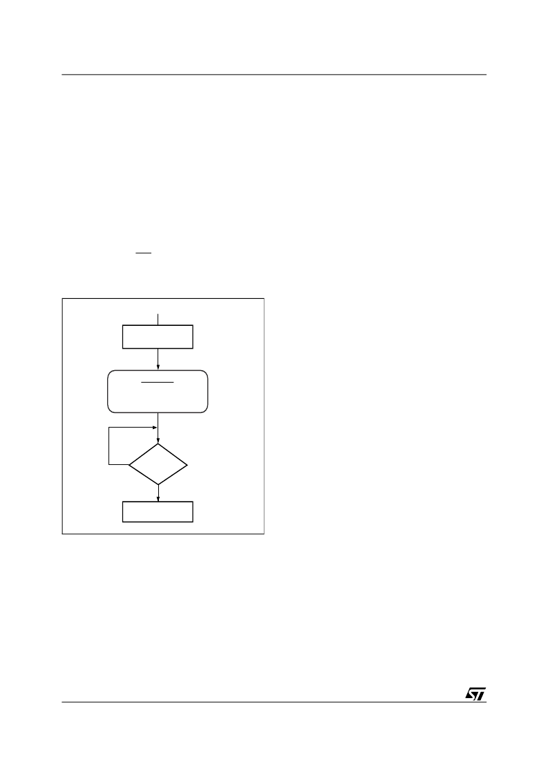
Figure 33. Enable Power-down Flow Chart
PLD Power Management
The power and speed of the PLDs are controlled
by the Turbo Bit (Bit 3) in PMMR0. By setting the
bit to '1,' the Turbo mode is off and the PLDs con-
sume the specified stand-by current when the in-
puts are not switching for an extended time of
70ns. The propagation delay time is increased by
10ns after the Turbo Bit is set to '1' (turned off)
when the inputs change at a composite frequency
of less than 15 MHz. When the Turbo Bit is reset
to '0' (turned on), the PLDs run at full power and
speed. The Turbo Bit affects the PLD’s DC power,
AC power, and propagation delay.
Blocking MCU control signals with the bits of
PMMR2 can further reduce PLD AC power con-
sumption.
SRAM Standby Mode (Battery Backup).
The
PSD supports a battery backup mode in which the
contents of the SRAM are retained in the event of
a power loss. The SRAM has Voltage Stand-by
(V
STBY
, PC2) that can be connected to an external
battery. When V
CC
becomes lower than V
STBY
then the PSD automatically connects to Voltage
Stand-by (V
STBY
, PC2) as a power source to the
SRAM. The SRAM Standby Current (I
STBY
) is typ-
ically 0.5μA. The SRAM data retention voltage is
2V minimum. The Battery-on Indicator (VBATON)
can be routed to PC4. This signal indicates when
the V
CC
has dropped below V
STBY
.
Enable APD
Set PMMR0 Bit 1 = 1
PSD in Power
Down Mode
ALE/AS idle
for 15 CLKIN
clocks
RESET
Yes
No
OPTIONAL
Disable desired inputs to PLD
by setting PMMR0 bits 4 and 5
and PMMR2 bits 2 through 6.
AI02892
相關(guān)PDF資料 |
PDF描述 |
|---|---|
| PSD9134V15JT | Flash In-System Programmable ISP Peripherals For 8-bit MCUs |
| PSD9134V15MT | Flash In-System Programmable ISP Peripherals For 8-bit MCUs |
| PSD9134V20MT | Flash In-System Programmable ISP Peripherals For 8-bit MCUs |
| PSD9134V70MT | Flash In-System Programmable ISP Peripherals For 8-bit MCUs |
| PSD9134V90MIT | Flash In-System Programmable ISP Peripherals For 8-bit MCUs |
相關(guān)代理商/技術(shù)參數(shù) |
參數(shù)描述 |
|---|---|
| PSD9134V12JIT | 制造商:STMICROELECTRONICS 制造商全稱:STMicroelectronics 功能描述:Flash In-System Programmable ISP Peripherals For 8-bit MCUs |
| PSD9134V12JT | 制造商:STMICROELECTRONICS 制造商全稱:STMicroelectronics 功能描述:Flash In-System Programmable ISP Peripherals For 8-bit MCUs |
| PSD9134V12MIT | 制造商:STMICROELECTRONICS 制造商全稱:STMicroelectronics 功能描述:Flash In-System Programmable ISP Peripherals For 8-bit MCUs |
| PSD9134V12MT | 制造商:STMICROELECTRONICS 制造商全稱:STMicroelectronics 功能描述:Flash In-System Programmable ISP Peripherals For 8-bit MCUs |
| PSD9134V15JIT | 制造商:STMICROELECTRONICS 制造商全稱:STMicroelectronics 功能描述:Flash In-System Programmable ISP Peripherals For 8-bit MCUs |
發(fā)布緊急采購(gòu),3分鐘左右您將得到回復(fù)。