- 您現在的位置:買賣IC網 > PDF目錄374645 > S1DL (Taiwan Semiconductor Co., Ltd.) 1.0 AMP. Surface Mount Rectifiers PDF資料下載
參數資料
| 型號: | S1DL |
| 廠商: | Taiwan Semiconductor Co., Ltd. |
| 英文描述: | 1.0 AMP. Surface Mount Rectifiers |
| 中文描述: | 1.0安培。表面貼裝二極管 |
| 文件頁數: | 1/2頁 |
| 文件大小: | 49K |
| 代理商: | S1DL |
- 480 -
0
0
0.114(2.9)
0.106(2.7)
0
0
0
(
0
0
DETAIL "A", SCALE=20/1
A
5
O
5
O
0.15(3.8)
0.134(3.4)
0
0
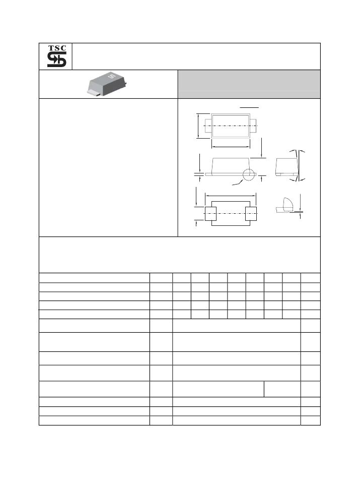
S1AL
THRU
S1ML
1.0 AMP. Surface Mount Rectifiers
Voltage Range
50 to 1000 Volts
Current
1.0 Ampere
Sub SMA
Features
For surface mounted application
Glass passivated junction chip.
Low-PROFILE PACKAGE
Ideal for automated placement
Low power loss, high efficiency
High temperature soldering:
260
o
C / 10 seconds at terminals
Mechanical Data
Case: JEDEC DO-219-AB(SMF) plastic case
Polarity: Color band denotes cathode end
Packaging: 12mm tape per EIA STD RS-481
Weight: approx. 15mg
Dimensions in inches and (millimeters)
Maximum Ratings and Electrical Characteristics
Rating at 25
℃
ambient temperature unless otherwise specified.
Single phase, half wave, 60 Hz, resistive or inductive load.
For capacitive load, derate current by 20%
Type Number
Maximum Recurrent Peak Reverse Voltage
Maximum RMS Voltage
Symbol
S1AL S1BL S1DL S1GL S1JL S1KL S1ML
Units
V
RRM
50
100 200 400 600 800 1000
V
RMS
35
70
140 280 420 560 700
V
DC
50
100 200 400 600 800 1000
1ALYM 1BLYM
1DLYM
1GLYM
1JLYM
1KLYM
1MLYM
V
V
V
Maximum DC Blocking Voltage
Marking Code (Note 3)
Maximum Average Forward Rectified
Current @T
L
=110
℃
Peak Forward Surge Current, 8.3 ms Single
Half Sine-wave Superimposed on Rated
Load (JEDEC method )
Maximum Instantaneous Forward Voltage
@ 1.0A
Maximum DC Reverse Current @ T
A
=25
℃
at Rated DC Blocking Voltage @ T
A
=125
℃
Typical Thermal Resis tance (Note 2)
I
(AV)
1.0
A
I
FSM
30
A
V
F
1.1
V
I
R
5
50
uA
uA
R
θ
JL
R
θ
JA
Cj
T
J
T
STG
25
85
30
85
℃
/W
Typical Junction Capacitance ( Note 1 )
9
pF
℃
℃
Operating Temperature Range
-55 to +150
-55 to +150
Storage Temperature Range
Notes: 1. Measured at 1 MHz and Applied V
=4.0 Volts
2. Measured on P.C. Board with 0.2 x 0.2” (5.0 x 5.0mm) Copper Pad Areas.
3. 1ALYM: 1=1A, A=50V, L-Low Profile, Y-Year Code, M-Month Code.
相關PDF資料 |
PDF描述 |
|---|---|
| S1GL | 1.0 AMP. Surface Mount Rectifiers |
| S2-0209 | High Linearity Position Sensing Detector with Signal Processing Circuit |
| S200-50 | 200 WATTS - 50 VOLTS 30MHZ |
| S2000N | RADIATION HARDENED HIGH EFFICIENCY, 5 AMP SWITCHING REGULATORS |
| S2002 | Dual Serial Backplane Device(用于高速串行數據傳送的雙串行收發器) |
相關代理商/技術參數 |
參數描述 |
|---|---|
| S1D-L | 制造商:MCC 制造商全稱:Micro Commercial Components 功能描述:1 Amp Silicon Rectifier 50 to 1000 Volts |
| S1DL R2 | 制造商:SKMI/Taiwan 功能描述:Diode Switching 200V 1.5A 2-Pin Sub SMA T/R |
| S1D-LTP | 制造商:Micro Commercial Components (MCC) 功能描述:Diode Switching 200V 1A 2-Pin SMB T/R |
| S1D-M3/5AT | 制造商:Vishay Semiconductors 功能描述:1A,200V,SMRECTIFIER |
| S1D-M3/61T | 制造商:Vishay Semiconductors 功能描述:1A,200V,SMRECTIFIER |
發布緊急采購,3分鐘左右您將得到回復。