- 您現在的位置:買賣IC網 > PDF目錄374702 > SB156G (Taiwan Semiconductor Co., Ltd.) High Current 15, 25, 35 AMPS. Single Phase Glass Passivated Bridge Rectifiers PDF資料下載
參數資料
| 型號: | SB156G |
| 廠商: | Taiwan Semiconductor Co., Ltd. |
| 元件分類: | 參考電壓二極管 |
| 英文描述: | High Current 15, 25, 35 AMPS. Single Phase Glass Passivated Bridge Rectifiers |
| 中文描述: | 高電流15,25,35安培。單相玻璃鈍化整流橋 |
| 文件頁數: | 1/2頁 |
| 文件大小: | 70K |
| 代理商: | SB156G |
- 770 -
AC
DIA .193(4.9)
HOLE FOR #8 SCREW
.692(17.6)
.612(15.5)
1.14(29.0)
1.01(25.7)
.25(6.35)
.442(11.23)
.432(10.97)
1.14(29.0)
1.01(25.7)
.692(17.6)
.612(15.5)
.602(15.3
.522(13.3
.752(19.1)
.672(17.1)
.93(23.5
.81(20.5
.490(12.4)
.410(10.4)
.040(1.0)
DIA TYP
DIA .193(4.9)
HOLE FOR #8 SCREW
.442(11.23)
.432(10.97)
1.14(29.0)
1.01(25.7)
.752(19.1)
.672(17.1)
.752(19.1)
.672(17.1)
1.14(29.0)
1.01(25.7)
1.2(30.5)
MIN.
DIA .193(4.9)
HOLE FOR #8 SCREW
.692(17.6)
.612(15.5)
1.14(29.0)
1.01(25.7)
.25(6.35)
.034(0.86)
.030(0.76)
.442(11.23)
.432(10.97)
.692(17.6)
.612(15.5)
1.14(29.0)
1.01(25.7)
.692(17.6
.612(15.5
.692(17.6)
.612(15.5)
.93(23.5)
.81(20.5)
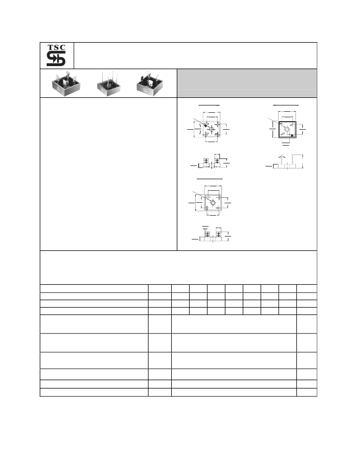
SB 15, 25, 35G SERIES
High Current 15, 25, 35 AMPS. Single Phase Glass Passivated Bridge Rectifiers
Voltage Range
50 to 1000 Volts
Current
15.0/25.0/35.0 Amperes
Features
UL Recognized File # E-96005
Metal case with an electrically isolated
epoxy
Rating to 1,000V PRV.
High efficiency
Mounting: thru hole for #8 screw
High temperature soldering guaranteed:
260
℃
/ 10 seconds at 5 lbs., ( 2.3 kg )
tension
Leads solderable per MIL-STD-202
Method 208
Isolated voltage from case to lead over
2000 volts
SB35 SB35-W
SB35-M
Dimensions in inches and (millimeters)
Maximum Ratings and Electrical Characteristics
Rating at 25
℃
ambient temperature unless otherwise specified.
Single phase, half wave, 60 Hz, resistive or inductive load.
For capacitive load, derate current by 20%
Type Number
Maximum Recurrent Peak Reverse Voltage
Maximum RMS Voltage
Maximum DC Blocking Voltage
Maximum Average Forward SB15
Rectified Current
SB25
@T
C
= 55
℃
SB35
Peak Forward Surge Current,
SB15
Single Sine-wave Superimposed on
SB25
Rated Load (JEDEC method )
SB35
Maximum Instantaneous Forward SB15 7.5A
Voltage Drop Per Element
SB25 12.5A
at Specified Current
SB35 17.5A
Maximum DC Reverse Current
at Rated DC Blocking Voltage Per Element
Typical Thermal Resistance (Note 1)
Symbol
-05
V
RRM
V
RMS
V
DC
-1
100
70
100
-2
200
140
200
-4
400
280
400
15.0
25.0
35.0
300
300
400
-6
600
420
600
-8
800 1000
560
800 1000
-10
Units
50
35
50
V
V
V
700
I
(AV)
A
I
FSM
A
V
F
1.1
V
I
R
10
2.0
uA
/
W
℃
R
θ
JC
T
J
,T
STG
℃
Operating and Storage Temperature Range
Notes: 1. Thermal Resistance from Junction to Case.
2. Suffix “W” - Wire Lead Structure/”M” - Terminal Location Face to Face.
-50 to +150
相關PDF資料 |
PDF描述 |
|---|---|
| SB160-05H | 50V, 16A Rectifier |
| SB160-05R | 50V, 16A Rectifier |
| SB160-09R | 90V, 16A Rectifier |
| SB20-03B | 30V, 2A Rectifier |
| SB20-03E | 30V, 2A Rectifier |
相關代理商/技術參數 |
參數描述 |
|---|---|
| SB156M | 制造商:TSC 制造商全稱:Taiwan Semiconductor Company, Ltd 功能描述:High Current 15 25 35 AMPS Single Phase Bridge Rectifiers |
| SB156W | 制造商:TSC 制造商全稱:Taiwan Semiconductor Company, Ltd 功能描述:High Current 15 25 35 AMPS Single Phase Bridge Rectifiers |
| SB157 | 制造商:TRSYS 制造商全稱:Transys Electronics 功能描述:Schottky cr Barrier Diode Wafer 157 x 106 Mils, 15 Volt, 20 Amp, 0.37VF. |
| SB157/106C015-20-W-AG/AL | 制造商:TRSYS 制造商全稱:Transys Electronics 功能描述:Schottky cr Barrier Diode Wafer 157 x 106 Mils, 15 Volt, 20 Amp, 0.37VF. |
| SB157/106C015-30-W-AG/AL | 制造商:TRSYS 制造商全稱:Transys Electronics 功能描述:Schottky cr Barrier Diode Wafer 157 x 106 Mils, 15 Volt, 30 Amp, 0.38VF. |
發布緊急采購,3分鐘左右您將得到回復。