- 您現在的位置:買賣IC網 > PDF目錄374709 > SB6G (Taiwan Semiconductor Co., Ltd.) Single Phase 6.0 AMPS. Glass Passivated Bridge Rectifiers PDF資料下載
參數資料
| 型號: | SB6G |
| 廠商: | Taiwan Semiconductor Co., Ltd. |
| 英文描述: | Single Phase 6.0 AMPS. Glass Passivated Bridge Rectifiers |
| 中文描述: | 單相6.0安培。玻璃鈍化整流橋 |
| 文件頁數: | 1/2頁 |
| 文件大小: | 111K |
| 代理商: | SB6G |
- 740 -
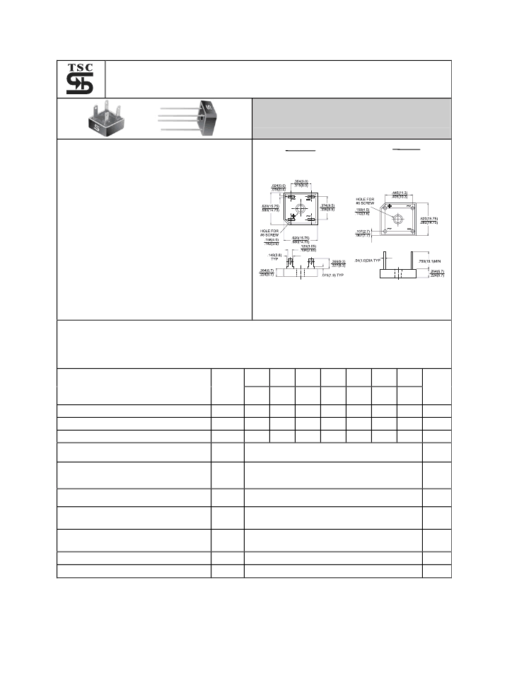
SB6G, SBT6G SERIES
Single Phase 6.0 AMPS. Glass Passivated Bridge Rectifiers
Voltage Range
50 to 1000 Volts
Current
6.0 Amperes
Features
UL Recognized File # E-96005
Glass passivated junction
Surge overload rating 175 amperes peak
Low forward voltage drop
Mounting position: Any
High temperature soldering guaranteed:
260
℃
/ 10 seconds / 0.375” ( 9.5mm )
lead length at 5 lbs., ( 2.3 kg ) tension
Small size, simple installation
Leads solderable per MIL-STD-202
Method 208
SBT-6 SB-6
Dimensions in inches and (millimeters)
Maximum Ratings and Electrical Characteristics
Rating at 25
℃
ambient temperature unless otherwise specified.
Single phase, half wave, 60 Hz, resistive or inductive load.
For capacitive load, derate current by 20%
Type Number
SB
601G
SBT
601G
50
35
50
SB
602G
SBT
602G
100
70
100
SB
603G
SBT
603G
200
140
200
SB
604G
SBT
604G
400
280
400
SB
605G
SBT
605G
600
420
600
SB
606G
SBT
606G
800 1000
560
800 1000
SB
607G
SBT
607G
Symbol
Units
Maximum Recurrent Peak Reverse Voltage
Maximum RMS Voltage
V
RRM
V
RMS
V
DC
V
V
V
700
Maximum DC Blocking Voltage
Maximum Average Forward Rectified Current
@T
A
= 50
℃
Peak Forward Surge Current, 8.3 ms Single
Half Sine-wave Superimposed on Rated
Load (JEDEC method )
Maximum Instantaneous Forward Voltage
@ 3.0A
Maximum DC Reverse Current @ T
A
=25
℃
at Rated DC Blocking Voltage @ T
A
=125
℃
I
(AV)
6.0
A
I
FSM
175
A
V
F
1.1
10
500
22
7.3
V
uA
uA
I
R
Typical Thermal Resistance (Note 1)
(Note 2)
R
θ
JA
R
θ
JL
T
J
T
STG
℃
/W
Operating Temperature Range
-55 to +150
-55 to +150
℃
℃
Storage Temperature Range
Notes: 1. Unit Mounted on P.C.B. at 0.375” (9.5mm) Lead Length with 0.5 x 0.5” (12 x 12mm)
Copper Pads.
2. Unit Mounted on 2” x 3” x 0.25” Al. Plate.
相關PDF資料 |
PDF描述 |
|---|---|
| SBT604G | Single Phase 6.0 AMPS. Glass Passivated Bridge Rectifiers |
| SBT605G | Single Phase 6.0 AMPS. Glass Passivated Bridge Rectifiers |
| SBT606G | Single Phase 6.0 AMPS. Glass Passivated Bridge Rectifiers |
| SB601G | Single Phase 6.0 AMPS. Glass Passivated Bridge Rectifiers |
| SB602G | Single Phase 6.0 AMPS. Glass Passivated Bridge Rectifiers |
相關代理商/技術參數 |
參數描述 |
|---|---|
| SB6HM2 | 制造商:Thomas & Betts 功能描述:6SOL-8SOL SPLIT BOLT PK/2 |
| SB-6N | 制造商:Fuji Electric 功能描述: |
| SB6N2MG1334PA600 | 制造商:SOURIAU 功能描述:CONNECTOR |
| SB-6NB | 制造商:Fuji Electric 功能描述: |
| SB6S1A1T2AGE | 制造商:GREATECS 制造商全稱:GREATECS 功能描述:Sub-Miniature Slide Switches |
發布緊急采購,3分鐘左右您將得到回復。