- 您現在的位置:買賣IC網 > PDF目錄382479 > SBTC-2-10-75L (MINI-CIRCUITS) Power Splitter/Combiners 2 Way-0∑ 75з 10 to 1000 MHz PDF資料下載
參數資料
| 型號: | SBTC-2-10-75L |
| 廠商: | MINI-CIRCUITS |
| 元件分類: | 衰減器 |
| 英文描述: | Power Splitter/Combiners 2 Way-0∑ 75з 10 to 1000 MHz |
| 中文描述: | 10 MHz - 1000 MHz RF/MICROWAVE SPLITTER AND COMBINER, 1.4 dB INSERTION LOSS |
| 封裝: | CASE AT1029, 5 PIN |
| 文件頁數: | 1/1頁 |
| 文件大小: | 96K |
| 代理商: | SBTC-2-10-75L |
Splitter Electrical Specifications
Features
low insertion loss, 0.8 dB typ.
excellent amplitude unbalance, 0.15 dB typ.
very good phase unbalance, 1.0 deg. typ.
small size, 0.166"x0.150"x0.155"
temperature stable, BLUE CELL base
solder plated leads for excellent solderability
small size
low cost
patent pending
Applications
cellular
UHF/VHF receivers/transmitters
L
Typ. Min.
M
Typ. Min.
U
Typ. Min.
FREQ.
RANGE
(MHz)
PHASE
UNBALANCE
(Degrees)
L
Max.
U
Max.
M
Max.
ISOLATION
(dB)
INSERTION LOSS (dB)
ABOVE 3.0 dB
L
Typ. Max.
M
Typ. Max.
U
Typ. Max.
AMPLITUDE
UNBALANCE
(dB)
L
Max.
U
Max.
M
Max.
f
L
-f
U
10-1000
35
20
28
20
21
17
0.7
1.2
0.6
1.2
0.7
1.4
3
3
5
0.7
0.6
0.6
L = low range [f
L
to 10 f
L
]
M = mid range [10 f
L
to f
U
/2] U = upper range [f
U
/2 to f
U
]
Typical Performance Data
Frequency
(MHz)
Insertion Loss
(dB)
S-1
3.74
3.73
3.73
3.74
3.77
Amplitude
Unbalance
(dB)
Isolation
(dB)
VSWR
S
(dB)
S-2
3.42
3.43
3.44
3.46
3.54
VSWR
1
VSWR
2
Phase
Unbalance
(deg.)
10.00
50.00
70.00
100.00
200.00
0.31
0.30
0.29
0.29
0.22
37.11
40.95
39.94
38.55
35.75
0.66
0.14
0.14
0.13
0.09
1.04
1.02
1.03
1.04
1.10
1.33
1.29
1.28
1.27
1.26
1.23
1.21
1.21
1.20
1.21
300.00
400.00
500.00
600.00
700.00
3.79
3.80
3.85
3.87
3.82
3.57
3.60
3.69
3.75
3.75
0.22
0.20
0.16
0.12
0.07
32.58
30.37
28.37
25.52
24.07
0.54
0.60
0.64
0.74
0.75
1.13
1.17
1.20
1.18
1.19
1.27
1.28
1.24
1.21
1.20
1.22
1.26
1.27
1.28
1.30
800.00
850.00
900.00
950.00
1000.00
3.83
3.84
3.85
3.86
3.86
3.82
3.86
3.90
3.93
3.98
0.03
0.03
0.06
0.08
0.11
22.85
22.40
22.15
21.95
21.68
0.77
0.73
0.69
0.64
0.58
1.19
1.18
1.17
1.18
1.18
1.26
1.23
1.23
1.25
1.25
1.32
1.31
1.32
1.35
1.35
No Leads
CASE STYLE:AT790
PRICE:$3.49 ea. QTY (25)
$2.69 ea. QTY (1000)
Leads
CASE STYLE:AT1029
PRICE:$3.64 ea. QTY (25)
$2.84 ea. QTY (1000)
SBTC-2-10-75
NEW!
SBTC-2-10-75L
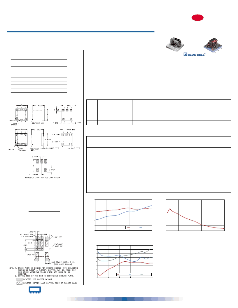
Outline Drawing
AT790
Demo Board MCL P/N: TB-274
Suggested PCB Layout (PL-152)
Reflow Solder Assembly
Silver-bearing solder (Sn/Pb/Ag 62/36/2%) is recommended;
however, tin-lead eutectic (Sn/Pb 63/37%) may be used.
For temperature profiles, see Application Note AN-40-004
AT1029
A
B
C
D
E
F
G
H
J
K
L
wt.
.166 .150 .155 .050 .037 .025 .012 .060 .184 .030 .004 grams
4.22 3.81 3.94 1.27 0.94 0.64 0.30 1.52 4.67 0.76 0.10
.10
AT790
A
B
C
D
E
F
G
H
J
K
wt.
.150 .150 .150 .050 .030 .025 .028 .050 .160 .030
3.81 3.81 3.81 1.27 0.76 0.64 0.71 1.27 4.06 0.76
grams
.10
Outline Dimensions ( )
inch
mm
SBTC-2-10-75L
ISOLATION
20
25
30
35
40
45
50
0
200
400
600
800
1000
FREQUENCY (M H z)
I
at RF level of -10 dBm
SBTC-2-10-75L
VSWR
1.00
1.05
1.10
1.15
1.20
1.25
1.30
1.35
1.40
0
200
400
FREQUENCY (MHz)
600
800
1000
V
#S-VSWR
#1-VSWR
#2-VSWR
at RF level of -10 dBm
SBTC-2-10-75L
INSERTION LOSS
3.0
3.2
3.4
3.6
3.8
4.0
4.2
0
200
400
600
800
1000
FREQUENCY (M H z)
I
S-1(dB)
S-2(dB)
at RF level of -10 dBm
REV. C
ED-9226/2
Maximum Ratings
Operating Temperature
Storage Temperature
Power Input (as a splitter)
Internal Dissipation
Pin Connections
SUM PORT
PORT 1
PORT 2
GROUND
NOT USED
6
3
4
1,2
5
-40
°
C to 85
°
C
-55
°
C to 100
°
C
0.5W max.
0.125W max.
AT1029
AT790 & AT1029
2 Way-0° 75
10 to 1000 MHz
Surface Mount
Power Splitter/Combiners
INTERNET
http://www.minicircuits.com
P.O. Box 350166, Brooklyn, New York 11235-0003 (718) 934-4500 Fax (718) 332-4661
Distribution Centers
NORTH AMERICA 800-654-7949 417-335-5935 Fax 417-335-5945 E
UROPE 44-1252-832600
Fax 44-1252-837010
Mini-Circuits
ISO 9001 CERTIFIED
相關PDF資料 |
PDF描述 |
|---|---|
| SBTC-2-10-75_75L | Power Splitter/Combiners 2 Way-0∑ 75з 10 to 1000 MHz |
| SBTC-2-10 | Power Splitter/Combiners 2 Way-0∑ 50з 5 to 1000 MHz |
| SBTC-2-10L | Power Splitter/Combiners 2 Way-0∑ 50з 5 to 1000 MHz |
| SBTC-2-10_10L | Power Splitter/Combiners 2 Way-0∑ 50з 5 to 1000 MHz |
| SBTC-2-20 | Power Splitter/Combiners 2 Way-0∑ 50з 200 to 2000 MHz |
相關代理商/技術參數 |
參數描述 |
|---|---|
| SBTC-2-10L | 制造商:MINI 制造商全稱:Mini-Circuits 功能描述:Power Splitter/Combiners 2 Way-0∑ 50з 5 to 1000 MHz |
| SBTC-2-15-75 | 制造商:MINI 制造商全稱:Mini-Circuits 功能描述:Surface Mount, Micro-Miniature Power Splitter/Combiners 2 Way-0∑ 75з 500 to 1500 MHz |
| SBTC-2-15-75_75L | 制造商:MINI 制造商全稱:Mini-Circuits 功能描述:Surface Mount, Micro-Miniature Power Splitter/Combiners 2 Way-0∑ 75з 500 to 1500 MHz |
| SBTC-2-15-75L | 制造商:MINI 制造商全稱:Mini-Circuits 功能描述:Surface Mount, Micro-Miniature Power Splitter/Combiners 2 Way-0∑ 75з 500 to 1500 MHz |
| SBTC-2-20 | 制造商:MINI 制造商全稱:Mini-Circuits 功能描述:Power Splitter/Combiners 2 Way-0∑ 50з 200 to 2000 MHz |
發布緊急采購,3分鐘左右您將得到回復。