- 您現在的位置:買賣IC網 > PDF目錄376348 > SG2731N (MICROSEMI CORP) DC MOTOR PULSE WIDTH MODULATOR PDF資料下載
參數資料
| 型號: | SG2731N |
| 廠商: | MICROSEMI CORP |
| 元件分類: | 運動控制電子 |
| 英文描述: | DC MOTOR PULSE WIDTH MODULATOR |
| 中文描述: | BRUSH DC MOTOR CONTROLLER, 0.4 A, PDIP16 |
| 封裝: | ROHS COMPLIANT, PLASTIC, DIP-16 |
| 文件頁數: | 1/5頁 |
| 文件大小: | 140K |
| 代理商: | SG2731N |
SG1731/SG2731/SG3731
4/90 Rev 1.3 9/99
Copyright
1999
L
IN
F
IN
ITY
Microelectronics Inc.
Garden
Grove,
FAX: (714) 893-2570
11861 Western Avenue
∞
CA
92841
1
(714) 898-8121
∞
DC MOTOR PULSE WIDTH MODULATOR
FEATURES
±
3.5V to
±
15V control supply
±
2.5V to
±
22V driver supply
Dual 100mA source/sink output
drivers
5KHz to 350KHz oscillator range
High slew rate error amplifier
Adjustable deadband operation
Digital SHUTDOWN input
HIGH RELIABILITY FEATURES
- SG1731
Available to MIL-STD-883
LMI level “S” processing available
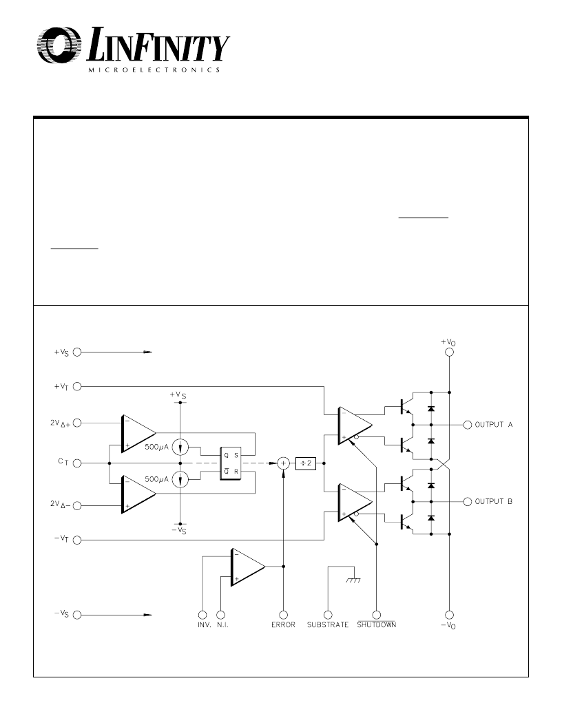
BLOCK DIAGRAM
DESCRIPTION
The SG1731 is a pulse width modulator circuit designed specifically for DC motor
control. It provides a bi-directional pulse train output in response to the magnitude
and polarity of an analog error signal input. The device is useful as the control
element in motor-driven servo systems for precision positioning and speed control,
as well as in audio modulators and amplifiers using carrier frequencies to 350 KHz.
The circuit contains a triangle waveform oscillator, a wideband operational amplifier
for error voltage generation, a summing/scaling network for level-shifting the
triangle waveform, externally programmable PWM comparators and dual
±
100mA,
±
22V totem pole drivers with commutation diodes for full bridge output. A
SHUTDOWN terminal forces the drivers into a floating high-impedance state when
driven LOW. Supply voltage to the control circuitry and to the output drivers may be
from either dual positive and negative supplies, or single-ended.
相關PDF資料 |
PDF描述 |
|---|---|
| SG1731 | DC MOTOR PULSE WIDTH MODULATOR |
| SG1731J | DC MOTOR PULSE WIDTH MODULATOR |
| SG2842Y | CURRENT MODE PWM CONTROLLER |
| SG3842D | CURRENT MODE PWM CONTROLLER |
| SG3842DM | CURRENT MODE PWM CONTROLLER |
相關代理商/技術參數 |
參數描述 |
|---|---|
| SG276 | 制造商:未知廠家 制造商全稱:未知廠家 功能描述:SG276 |
| SG277 | 制造商:KODENSHI 制造商全稱:KODENSHI KOREA CORP. 功能描述:PhotoInterrupter(Transimissive) |
| SG278 | 制造商:KODENSHI 制造商全稱:KODENSHI KOREA CORP. 功能描述:PhotoInterrupter(Transimissive) |
| SG27N | 制造商:未知廠家 制造商全稱:未知廠家 功能描述: |
| SG28 | 制造商:Ametherm Inc 功能描述: |
發布緊急采購,3分鐘左右您將得到回復。