- 您現在的位置:買賣IC網 > Datasheet目錄46 > SI786LSG-E3 (Vishay Siliconix)IC REG QD BUCK/LINEAR 28SSOP Datasheet資料下載
參數資料
| 型號: | SI786LSG-E3 |
| 廠商: | Vishay Siliconix |
| 文件頁數: | 3/16頁 |
| 文件大小: | 236K |
| 描述: | IC REG QD BUCK/LINEAR 28SSOP |
| 標準包裝: | 225 |
| 拓撲: | 降壓(降壓)(2),線性(LDO)(2) |
| 功能: | 任何功能 |
| 輸出數: | 4 |
| 頻率 - 開關: | 300kHz,200kHz |
| 電壓/電流 - 輸出 1: | 控制器 |
| 電壓/電流 - 輸出 2: | 控制器 |
| 電壓/電流 - 輸出 3: | 5V,5mA |
| 帶 LED 驅動器: | 無 |
| 帶監控器: | 無 |
| 帶序列發生器: | 無 |
| 電源電壓: | 5.5 V ~ 30 V |
| 工作溫度: | -10°C ~ 90°C |
| 安裝類型: | 表面貼裝 |
| 封裝/外殼: | 28-SSOP(0.209",5.30mm 寬) |
| 供應商設備封裝: | 28-SSOP |
| 包裝: | 散裝 |
Document Number: 70189
S-40807-Rev. J, 26-Apr-04
www.vishay.com
3
Vishay Siliconix
Si786
Product is End of Life 3/2014
Notes:
a. The algebraic convention whereby the most negative value is a minimum and the most positive a maximum.
b. Typical values are for DESIGN AID ONLY, not guaranteed nor subject to production testing.
c. The main switching outputs track the reference voltage. Loading the reference reduces the main outputs slightly according to the closed-loop
gain (AV
CL
) and the reference voltage load-regulation error. AV
CL
for the 3.3 V supply is unity gain. AV
CL
for the 5 V supply is 1.54.
d. Since the reference uses V
L
as its supply, its V+ line regulation error is insignificant.
e. Limits are for all temperature grades unless otherwise noted.
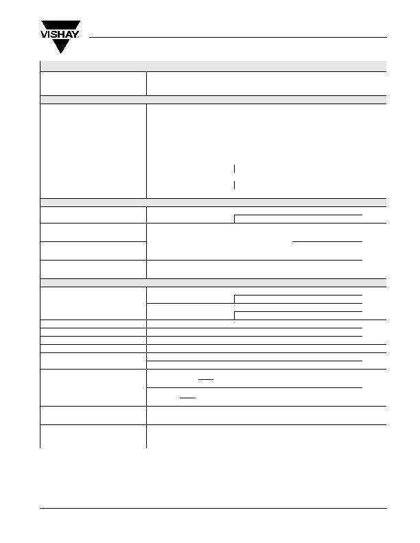
SPECIFICATIONS
Parameter
Specific Test Conditions
V+ = 15 V, I
VL
= I
REF
= 0 mA, SHDN
= ON
3
= ON
5
= 5 V
Other Digital Input Levels 0 V or 5 V, T
A
= T
MIN
to T
MAX
Limits
e
Unit
Min
a
Typ
b
Max
a
Internal Regulator and Reference
V
L
/FB
5
Switchover Voltage
Rising Edge of FB
5
, Hysteresis = 1 %
4.2
4.7
V
REF Output Voltage
No External Load
c
3.24
3.36
REF Fault Lockout Voltage
Falling Edge
2.4
3.2
REF Load Regulation
0 mA < I
L
< 5 mA
d
30 75 mV
V+ Shutdown Current
SHDN
= D
1
= D
2
= ON
3
= ON
5
= 0 V
V+ = 30 V
25 40
礎
V+ Standby Current
D
1
= D
2
= ON
3
= ON
5
= 0 V
V+ = 30 V
70 110
Si786DG/DRG/DSG
70 115
Quiescent Power Consumption (both
PWM controllers on)
D
1
= D
2
= 0 V, FB
5
= CS
5
= 5.25 V
FB
3
= CS
3
= 3.5 V
5.5 8.6
mV
Si786DG/DRG/DSG
5.5 9.0
V+ Off Current
FB
5
= CS
5
= 5.25 V, V
L
Switched Over to FB
5
30 60 礎
Comparators
D
1
, D
2
Trip Voltage
Falling Edge Hysteresis = 1 %
1.61
1.69
V
Si786DG/DRG/DSG 1.60
1.69
D
1
, D
2
Input Current
D
1
= D
2
= 0 V, 5 V
?100 nA
Q
1
, Q
2
Source Current
V
H
= 15 V, V
OUT
= 2.5 V
12 20 30
礎
Q
1
, Q
2
Sink Current
200 500 1000
Q
1
, Q
2
Output High Voltage
I
SOURCE
= 5 A, V
H
= 3 V
V
H
- 0.5
V
Q
1
, Q
2
Output Low Voltage
I
SINK
= 20 A, V
H
= 3 V
0.4
Quiescent V
H
Current
V
H
= 18 V, D
1
= D
2
= 5 V, No External Load
4 10 礎
Oscillator and Inputs/Outputs
Oscillator Frequency
SYNC = 3.3 V
270 300 330
kHz
Si786DG/DRG/DSG 260 300 330
SYNC = 0 V, 5 V
170 200 230
Si786DG/DRG/DSG 165 200 230
SYNC High Pulse Width
200
ns
SYNC Low Pulse Width
200
SYNC Rise/Fall Time
Not Tested
200
Oscillator SYNC Range
240
350 kHz
Maximum Duty Cycle
SYNC = 3.3 V
89 92
%
SYNC = 0 V, 5 V
92 95
Input Low Voltage
SHDN
, ON
3
, ON
5
SYNC
0.8
V
Input High Voltage
SHDN
, ON
3
, ON
5
2.4
SYNC
V
L
- 0.5
Input Current
SHDN
, ON
3
, ON
5
, V
IN
= 0 V, 5 V
?1 礎
DL
3
/DL
5
Sink/Source Current
V
OUT
= 2 V
1
A
DH
3
/DH
5
Sink/Source Current
BST
3
- LX
3
= BST
5
- LX
5
= 4.5 V, V
OUT
= 2 V
1
DL
3
/DL
5
On-Resistance
High or Low
7
?/DIV>
DH
3
/DH
5
On-Resistance
High or Low
BST
3
- LX
3
= BST
5
- LX
5
= 4.5 V
7
相關PDF資料 |
PDF描述 |
|---|---|
| SIC417CD-T1-E3 | IC REG DL BCK/LINEAR SYNC 32MLPQ |
| SP619EK-L/TR | IC HIGH CURRENT SW SOT23-6 |
| TC573302ECTTR | IC REG CTRLR SGL 3.3V SOT23A-5 |
| TC670ECHTR | IC FAN FAILURE DETECTOR SOT23A-6 |
| TC74A7-5.0VCTTRG | IC DGTL THERM SNSR 5.0V SOT23A-5 |
相關代理商/技術參數 |
參數描述 |
|---|---|
| SI786LSG-T1 | 功能描述:開關變換器、穩壓器與控制器 Dual 3.45V Step-Down RoHS:否 制造商:Texas Instruments 輸出電壓:1.2 V to 10 V 輸出電流:300 mA 輸出功率: 輸入電壓:3 V to 17 V 開關頻率:1 MHz 工作溫度范圍: 安裝風格:SMD/SMT 封裝 / 箱體:WSON-8 封裝:Reel |
| SI786LSG-T1-E3 | 功能描述:開關變換器、穩壓器與控制器 Dual 3.45V Step-Down RoHS:否 制造商:Texas Instruments 輸出電壓:1.2 V to 10 V 輸出電流:300 mA 輸出功率: 輸入電壓:3 V to 17 V 開關頻率:1 MHz 工作溫度范圍: 安裝風格:SMD/SMT 封裝 / 箱體:WSON-8 封裝:Reel |
| SI7872DP | 制造商:VISHAY 制造商全稱:Vishay Siliconix 功能描述:Dual N-Channel 30-V (D-S) MOSFET with Schottky Diode |
| SI7872DP-T1 | 功能描述:MOSFET 30V 10A 1.4W RoHS:否 制造商:STMicroelectronics 晶體管極性:N-Channel 汲極/源極擊穿電壓:650 V 閘/源擊穿電壓:25 V 漏極連續電流:130 A 電阻汲極/源極 RDS(導通):0.014 Ohms 配置:Single 最大工作溫度: 安裝風格:Through Hole 封裝 / 箱體:Max247 封裝:Tube |
| SI7872DP-T1-E3 | 功能描述:MOSFET 30V 10A 0.022Ohm RoHS:否 制造商:STMicroelectronics 晶體管極性:N-Channel 汲極/源極擊穿電壓:650 V 閘/源擊穿電壓:25 V 漏極連續電流:130 A 電阻汲極/源極 RDS(導通):0.014 Ohms 配置:Single 最大工作溫度: 安裝風格:Through Hole 封裝 / 箱體:Max247 封裝:Tube |
發布緊急采購,3分鐘左右您將得到回復。