- 您現(xiàn)在的位置:買賣IC網(wǎng) > PDF目錄98215 > TFP513PAP (TEXAS INSTRUMENTS INC) SPECIALTY CONSUMER CIRCUIT, PQFP64 PDF資料下載
參數(shù)資料
| 型號: | TFP513PAP |
| 廠商: | TEXAS INSTRUMENTS INC |
| 元件分類: | 消費(fèi)家電 |
| 英文描述: | SPECIALTY CONSUMER CIRCUIT, PQFP64 |
| 封裝: | 10 X 10 MM, 1.00 MM HEIGHT, 0.50 MM PITCH, HTQFP-64 |
| 文件頁數(shù): | 27/32頁 |
| 文件大小: | 1206K |
| 代理商: | TFP513PAP |
第1頁第2頁第3頁第4頁第5頁第6頁第7頁第8頁第9頁第10頁第11頁第12頁第13頁第14頁第15頁第16頁第17頁第18頁第19頁第20頁第21頁第22頁第23頁第24頁第25頁第26頁當(dāng)前第27頁第28頁第29頁第30頁第31頁第32頁
TFP513
TI PanelBus DIGITAL TRANSMITTER
SLLS611 AUGUST 2004
4
POST OFFICE BOX 655303
DALLAS, TEXAS 75265
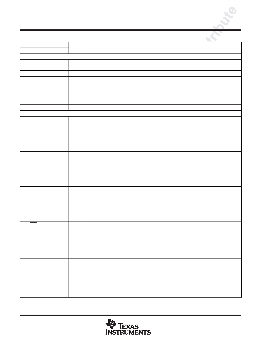
Terminal Functions (Continued)
TERMINAL
I/O
DESCRIPTION
NAME
NUMBER
I/O
DESCRIPTION
Input Pins (Continued)
DK3
6
I
This input pin is not used for the TFP513. It contains a weak pulldown resistor and may be left
unconnected. If a pullup resistor is connected to VDD, it must be in the range of 900 to 5 k.
HSYNC
4
I
Horizontal sync input
IDCK
IDCK+
56
57
I
Differential clock input. The TFP513 supports both single-ended and fully differential clock input modes.
In the single-ended clock input mode, the IDCK+ input (pin 57) must be connected to the single-ended
clock source and the IDCK input (pin 56) must be tied to GND. In the differential clock input mode, the
TFP513 uses the crossover point between the IDCK+ and IDCK signals as the timing reference for
latching incoming data DATA[23:0], DE, HSYNC, and VSYNC. The differential clock input mode is only
available in the low-signal-swing mode.
VSYNC
5
I
Vertical sync input
Configuration/Programming Pins
BSEL/SCL
15
I/O
Input bus select / I2C clock input. The operation of this pin depends on whether the I2C interface is
enabled or disabled. This pin is only 3.3-V tolerant.
When I2C is disabled (ISEL = low), a high level selects the 24-bit input, single-edge input mode. A low
level selects the 12-bit input, dual-edge input mode.
When I2C is enabled (ISEL = high), this pin functions as the I2C clock input (see the I2C register
descriptions section). In this configuration, this pin has an open-drain output that requires an external
5-k
pullup resistor connected to VDD.
DSEL/SDA
14
I/O
DSEL / I2C data. The operation of this pin depends on whether the I2C interface is enabled or disabled.
This pin is only 3.3-V tolerant.
When I2C is disabled (ISEL = low), this pin is used with BSEL and VREF to select the single-ended or
differential input clock mode (see the universal graphics controller interface modes section).
When I2C is enabled (ISEL = high), this pin functions as the I2C bidirectional data line. In this
configuration, this pin has an open-drain output that requires an external 5-k
pullup resistor connected
to VDD.
EDGE/HTPLG
9
I
Edge select / hot plug input. The operation of this pin depends on whether the I2C interface is enabled or
disabled. This input is 3.3-V tolerant only.
When I2C is disabled (ISEL = low), a high level selects the primary latch to occur on the rising edge of the
input clock IDCK+. A low level selects the primary latch to occur on the falling edge of the input clock
IDCK+. This is the case for both single-ended and differential input clock modes.
When I2C is enabled (ISEL = high), this pin monitors the hot plug detect signal (see the DVI or VESA
P&D and DFP standards). When used for hot-plug detection, this pin requires a series 1-k
resistor.
ISEL/RST
13
I
I2C interface select / I2C RESET (active low, asynchronous).
If ISEL is high, then the I2C interface is active. Default values for the I2C registers can be found in the I2C
register descriptions section.
If ISEL is low, then I2C is disabled and the chip configuration is specified by the configuration pins
(BSEL, DSEL, EDGE, VREF) and state pin (PD).
If ISEL is brought low and then back high, the I2C state machine is reset. The register values are
changed to their default values and are not preserved from before the reset.
MSEN
11
O
Monitor sense / programmable output 1. The operation of this pin depends on whether the I2C interface
is enabled or disabled. This pin has an open-drain output and is only 3.3-V tolerant. An external 5-k
pullup resistor connected to VDD is required on this pin.
When I2C is disabled (ISEL = low), a high level indicates a powered-on receiver is detected at the
differential outputs. A low level indicates a powered-on receiver is not detected. This function is valid
only in dc-coupled systems.
When I2C is enabled (ISEL = high), this output is programmable through the I2C interface (see the I2C
register descriptions).
相關(guān)PDF資料 |
PDF描述 |
|---|---|
| TFP6422PAP | SPECIALTY CONSUMER CIRCUIT, PQFP64 |
| TFP6424PAP | SPECIALTY CONSUMER CIRCUIT, PQFP64 |
| TFP9431CPAP | SPECIALTY CONSUMER CIRCUIT, PQFP64 |
| TG355ENK-7916 | 8.15 MHz, LOW PASS FILTER |
| TH355BDI-4957 | 4.43 MHz, BAND PASS FILTER |
相關(guān)代理商/技術(shù)參數(shù) |
參數(shù)描述 |
|---|---|
| TFP513PAPG4 | 制造商:TI 制造商全稱:Texas Instruments 功能描述:TI PANELBUS DIGITAL TRANSMITTER |
| TFP5N60 | 制造商:TAK_CHEONG 制造商全稱:Tak Cheong Electronics (Holdings) Co.,Ltd 功能描述:N-Channel Power MOSFET 4.5A, 600V, 2.4Ω |
| TFP61 | 制造商:HOFFMAN ENCLOSURES 功能描述:COOLING FAN PACKAGE, 6 IN;115V 50/60HZ;; 制造商:Pentair Technical Products / Hoffman 功能描述:COOLING FAN 140CFM 32W 制造商:HOFFMAN ENCLOSURES 功能描述:COOLING FAN, 140CFM, 32W 制造商:Pentair Technical Products / Hoffman 功能描述:COOLING FAN, 140CFM, 32W; Enclosure Material:ABS; Body Color:Black; External Height - Imperial:7.80"; External Height - Metric:198mm; External Width - Imperial:8.87"; External Width - Metric:225mm; External Depth - Imperial:3.8" ;RoHS Compliant: Yes |
| TFP61SS | 制造商:Pentair Technical Products / Hoffman 功能描述:115V,50/60Hz,36/32W,0.45/0.36A ;RoHS Compliant: Yes |
| TFP61UL12 | 制造商:HOFFMAN ENCLOSURES 功能描述:Fan;Cooling Fan Exhaust Package;115V,50/60Hz,36/32W,0.45/0.36A;5x8.5x9 制造商:Pentair Technical Products / Hoffman 功能描述:COOLING FAN, 60CFM, 32W; Enclosure Material:ABS; Body Color:Black; External Height - Imperial:7.8"; External Height - Metric:198mm; External Width - Imperial:8.9"; External Width - Metric:225mm; External Depth - Imperial:3.8" ;RoHS Compliant: Yes |
發(fā)布緊急采購,3分鐘左右您將得到回復(fù)。